
Electromagnetic wave absorber, manufacturing method thereof and electromagnetic wave anechoic room

a technology of electromagnetic waves and absorbers, which is applied in the direction of antennas, electrical equipment, etc., can solve the problems of increased transportation and installation costs, significant differences in the characteristics caused by the polarization plane, and extremely poor high-frequency characteristics

Active Publication Date: 2009-01-20
TDK CORPARATION +1
View PDF14 Cites 4 Cited by
  • Summary
  • Abstract
  • Description
  • Claims
  • Application Information

AI Technical Summary

Benefits of technology

[0027]These and other features and advantage of the present invention will be appreciated from reviewing of the following detailed description of the invention, along with the accompanying figures.

Problems solved by technology

For this reason, problems exist that the electromagnetic wave absorber becomes voluminous, thus causing the increases in transportation and installation costs.
In particular, in the case of the hollow wedge type comprised of sheet-type electromagnetic absorption members, there is the problem that the difference in the characteristics caused by the polarization plane is significantly large and high-frequency characteristics are extremely poor when the ridge of the wedge is perpendicular to the polarization plane of the electromagnetic wave.
However, with high frequencies, the characteristics in one of the cases (the case where the ridge of the wedge is perpendicular to the polarization plane of the electromagnetic wave) are extremely poor, and therefore the average characteristics also become poor.
Furthermore, in the case where the absorbers are arranged on sidewall surfaces as described above, the electromagnetic absorbers arranged in such a way that ridges of the wedges of them are horizontal are half of the total in number, and in such an arrangement, if the length is increased, a problem arises in terms of strength, such as bending.
On the other hand, the hollow pyramid type is often used since it has no difference in characteristics caused by a polarization plane and is also robust in terms of strength; however, it has poor low frequency characteristics in a range of 30 to 100 MHz in comparison with the hollow wedge type, whereby there is a problem that a length of the absorber should be increased.
However, there is a problem in the electromagnetic wave absorber having the configuration provided with an opening at a tip of a hollow cone-shaped body disclosed in Japanese Patent Application Laid-Open No. 2005-340730.
The problem is that although an electromagnetic wave can reach sintered ferrite compacts through the opening at higher frequencies, an absorption capability of the sintered ferrite compact is low at a high frequency of 1 GHz or higher, and so reflection becomes large.
Similarly, the rectangular pipe-shaped electromagnetic wave absorber disclosed in Japanese Patent Application Laid-Open No. 2-97096 and the electromagnetic wave absorber in which electromagnetic wave absorbing plates are crisscrossed disclosed in Japanese Patent Application Laid-Open No. 2001-127483 have also a problem of poor high frequency characteristics because of the exposure of a sintered ferrite compact.

Method used


Image

  • Electromagnetic wave absorber, manufacturing method thereof and electromagnetic wave anechoic room
  • Electromagnetic wave absorber, manufacturing method thereof and electromagnetic wave anechoic room
  • Electromagnetic wave absorber, manufacturing method thereof and electromagnetic wave anechoic room

Examples


first embodiment

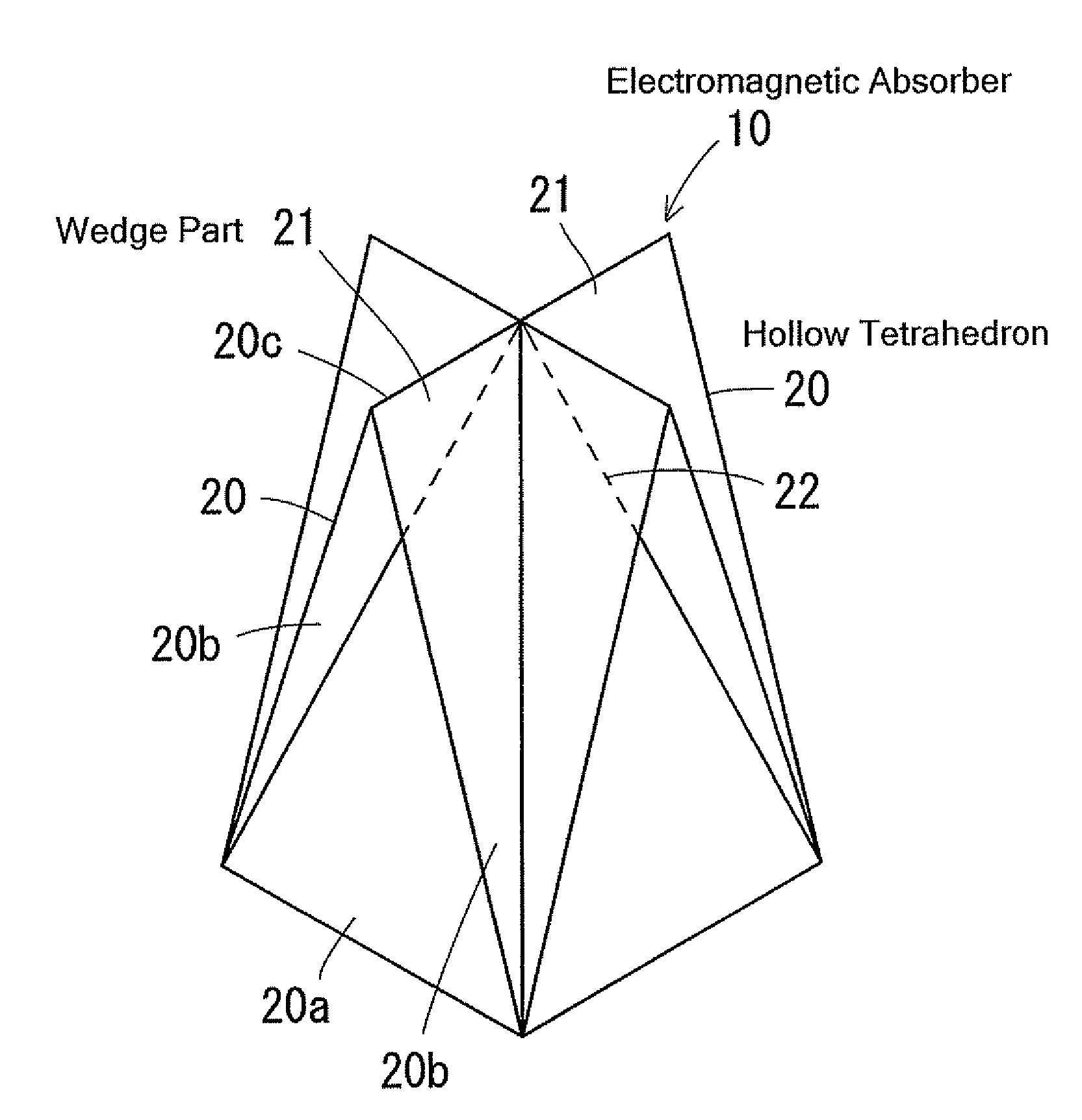
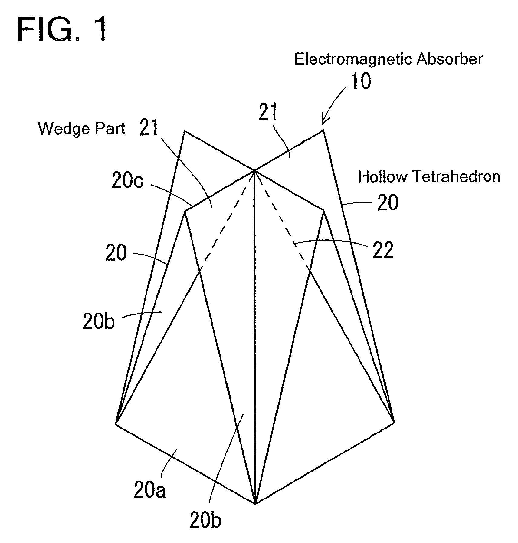
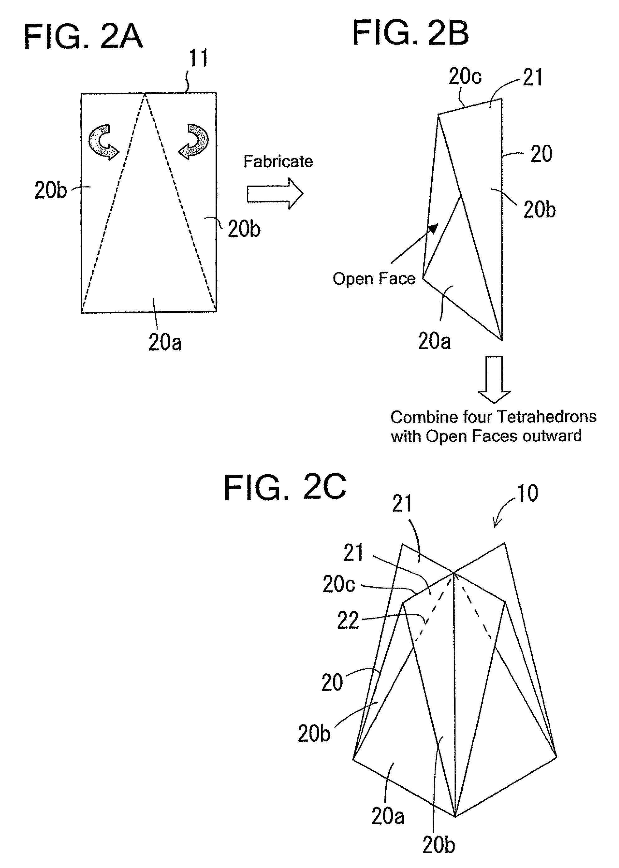
[0052]an electromagnetic wave absorber and the manufacturing method thereof according to the present invention will be described in reference to FIGS. 1 to 12. FIG. 1 shows the appearance of the electromagnetic absorber 10, which has the configuration shown in FIG. 2C, which is fabricated by folding two places of each quadrangular (including rectangular) sheet-type electromagnetic wave absorption member 11 as shown in FIG. 2 A to fabricate four hollow tetrahedrons 20 having one open face as shown in FIG. 2B and then by connecting and integrating the four hollow tetrahedrons 20 with one another in such a way that each triangular surface 20a opposite to each open face of the hollow tetrahedrons 20 defines each side face of a hollow quadrangular pyramid 22. If the triangular surface 20a has an isosceles triangle shape, the hollow quadrangular pyramid will have a regular quadrangular pyramid shape. Inverted triangular surfaces 20b that are folded and rise with respect to the triangular ...

second embodiment

[0071]In the second embodiment, adjusting length L1 of the ridge 21a of the wedge part 21 enables the electromagnetic wave absorption characteristics to be finely adjusted.

third embodiment

[0072]A third embodiment illustrating an electromagnetic wave absorber and the manufacturing method thereof according to the present invention is described in reference to FIGS. 14 to 16. FIG. 14 shows an appearance of the electromagnetic wave absorber 40, which has a configuration shown in FIG. 15 C, which is fabricated by folding two places of each quadrangular (including rectangular) sheet-type electromagnetic wave absorption member 11 as shown in FIG. 15A to fabricate four hollow tetrahedrons 20 having one open face as shown in FIG. 15B, and then by connecting and integrating the four hollow tetrahedrons 20 with one another in such a way that each open face of the hollow tetrahedrons 20 defines each side face of a hollow quadrangular pyramid 42. If the open face is in an isosceles triangle shape, the hollow quadrangular pyramid will have a regular quadrangular pyramid shape. The surface opposite to the open face of the hollow tetrahedron 20 is a triangular surface 20a, and inver...


PUM


Abstract

An electromagnetic wave absorber has a configuration in which at least three hollow tetrahedrons, each having one open face, are connected to one another so that each surface opposite to a respective open face of the hollow tetrahedrons defines a respective side face of a hollow pyramid. Preferably, the electromagnetic wave absorber is made of sheet electromagnetic wave absorption members, which have a corrugated board structure in which at least one sheet includes an electrically conductive material. The electromagnetic wave absorber is low-cost, has reduced transport volume, excellent electromagnetic wave absorption characteristics from low frequency to high frequency with a shorter absorber length, has no or small difference in characteristics due to polarization plane, is lightweight and high in structural strength, and easy to manufacture and install.

Description

BACKGROUND OF THE INVENTION[0001]1. Field of the Invention[0002]The present invention relates to an electromagnetic wave absorber that is preferably used for an electromagnetic wave anechoic room or the like and a method of manufacturing the electromagnetic wave absorber, and to an electromagnetic wave anechoic room.[0003]2. Description of the Prior Art[0004]An electromagnetic wave anechoic room for EMC (Electromagnetic Compatibility) has been widely put into practical use as an examination site for measuring electromagnetic wave noise radiated from various types of electronic equipment and evaluating tolerance of electronic equipment interfered by external electromagnetic wave noise. Also, in recent years, there is a movement that the electromagnetic wave anechoic room is used for a place (CALTS=Calibration Test Site) to calibrating an antenna for radiation noise measurement.[0005]Electromagnetic wave absorbers are installed on a ceiling and walls of an electromagnetic wave anechoi...

Claims


Application Information

Patent Timeline
Patent Type & Authority Patents(United States)
IPC IPC(8): H01Q17/00
CPCH01Q17/008
Inventor KURIHARA, HIROSHISAITO, TOSHIFUMIKASABO, MIKISUGAHARA, TORUTANOUE, TAKASHIMATSUMURA, KAZUYA
Owner TDK CORPARATION
Learn More