Electromagnetic wave abosrber

a technology of electromagnetic waves and absorbers, applied in the field of electromagnetic wave absorbers, can solve the problems of imposing limitations on the building site, difficult to apply this absorber to an anechoic chamber that requires high-level characteristics, and difficulty in prior art to implement etc., to achieve excellent electromagnetic wave absorbing characteristics and reduce thickness

Inactive Publication Date: 2002-03-19
TDK CORPARATION
View PDF13 Cites 17 Cited by
  • Summary
  • Abstract
  • Description
  • Claims
  • Application Information

AI Technical Summary

Benefits of technology

It is an object of the invention to provide an electromagnetic wave absorber having a reduced thickness and an excellent electromagnetic wave absorbing characteristic.
According to the electromagnetic wave absorber of the embodiment, a low-priced anechoic chamber that exhibits high performance will be implemented.

Problems solved by technology

As thus described, it is difficult in prior art to implement thin wave absorbers that exhibit excellent electromagnetic wave absorbing characteristics.
It is therefore difficult to apply this absorber to an anechoic chamber that requires high-level characteristics.
However, if the thickness of the absorber is increased, the size of the chamber is required to be increased to obtain a greater effective space in the chamber, which will impose a limitation on the building site and increase building costs.
Manufacturing costs are thereby increased.

Method used


Image

  • Electromagnetic wave abosrber
  • Electromagnetic wave abosrber
  • Electromagnetic wave abosrber

Examples


second example

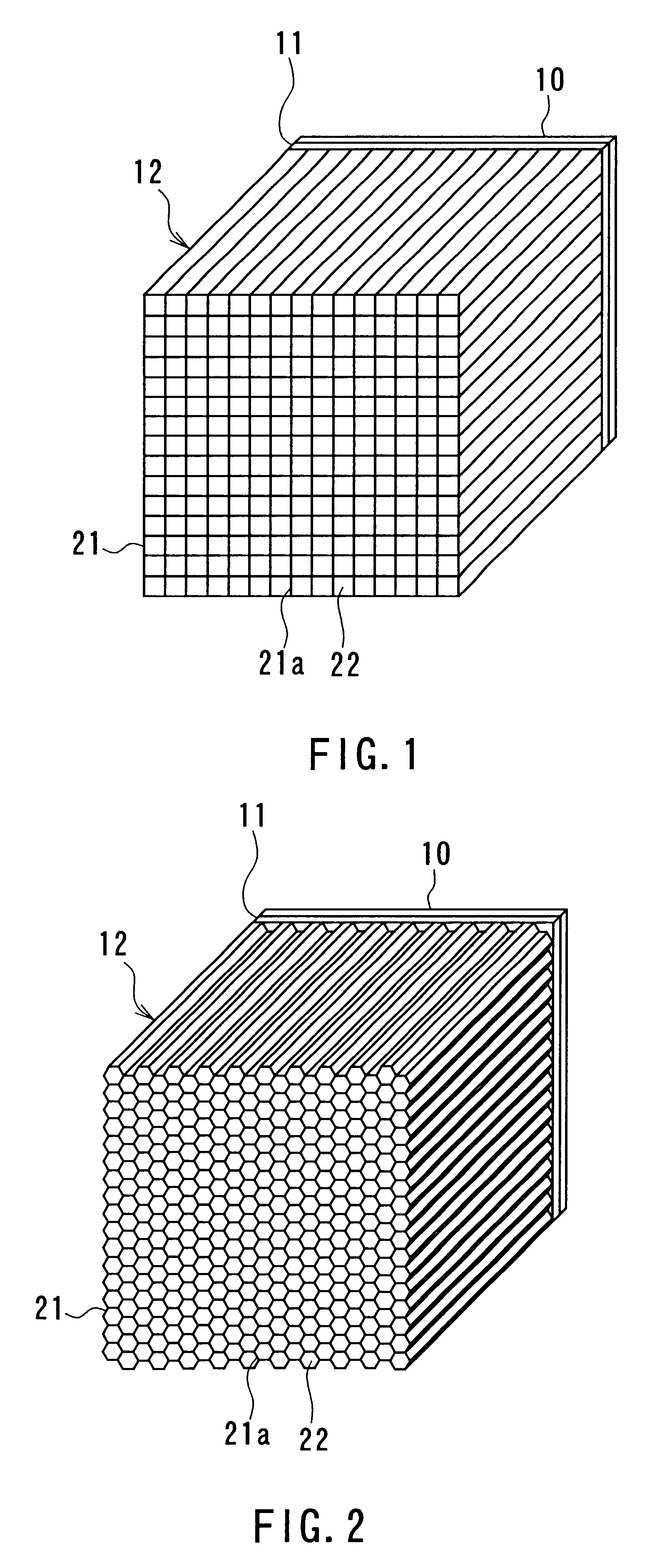
In a second example ferrite paper was utilized. This paper was made of hydrous inorganic compound consisting of glass fiber, aramide fiber and magnesium silicate whose weight ratio was 2:1:1 with which 70 weight % of Mn--Mg--Zn-type ferrite powder was mixed. Sheets of this paper were arranged to form a grid with a spacing of 20 mm to make the structure 21. This paper was formed through a paper fabricating technique and pressing. Each space between adjacent ones of the elements 21a of the structure 21 was filled with the dielectric loss material 22 made of molded Styrofoam containing graphite. The second wave absorber section 12 as shown in FIG. 1 was thus fabricated.

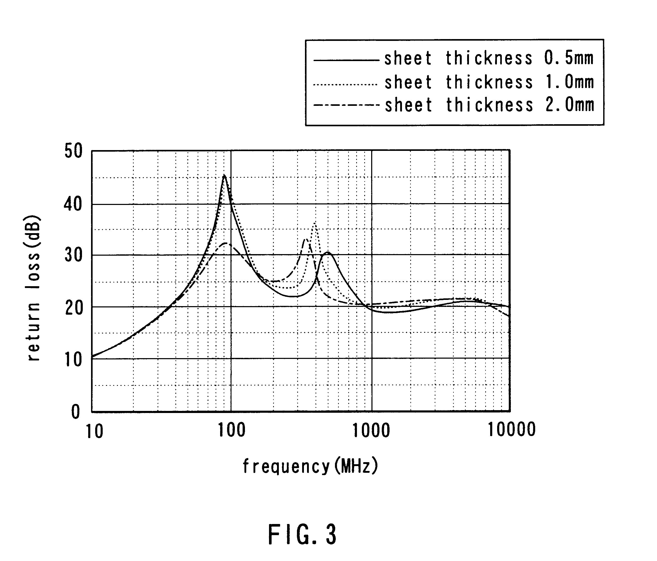
In the second example three types of second wave absorber sections 12 having the above-described configuration were fabricated. The ferrite paper had a thickness of 1.0 mm. The amounts of graphite contained in the molded Styrofoam were 6, 8 and 11 grams per liter, respectively. For comparison with the sections 12, refere...

third example

In a third example ferrite paper was utilized. This paper was made of hydrous inorganic compound consisting of glass fiber, aramide fiber and magnesium silicate whose weight ratio was 2:1:1 with which 70 weight % of Mn--Mg--Zn-type ferrite powder was mixed. Sheets of this paper were arranged to form a honeycomb to make the structure 21. This paper was formed through a paper fabricating technique and pressing. The space between adjacent ones of the elements 21a of the structure 21 was 20 mm. Next, a conductive coating that contains graphite was applied to surfaces of the elements 21a to form the dielectric loss materials 22. The second wave absorber section 12 as shown in FIG. 2 was thus fabricated.

In the third example three types of second wave absorber sections 12 having the above-described configuration were fabricated. The ferrite paper of these sections 12 had a thickness of 1.0 mm. The amounts of graphite contained in the entire volume of the respective second wave absorber sec...


PUM

PropertyMeasurementUnit
thicknessaaaaaaaaaa
thicknessaaaaaaaaaa
thicknessaaaaaaaaaa

Abstract

An electromagnetic wave absorber comprises: an electromagnetic wave reflector made of a metal plate; a tile-shaped first electromagnetic wave absorber section containing ferrite as a magnetic material and having surfaces one of which is adjacent to the wave reflector; and a second electromagnetic wave absorber section adjacent to the other surface of the first wave absorber section. The second wave absorber section includes a structure and a dielectric loss material. The structure includes a plurality of plate-shaped elements each of which is made of a magnetic loss material. These elements have surfaces that are located with specific spacing and orthogonal to the other surface of the first wave absorber section. The dielectric loss material is located at least part of the spaces between adjacent ones of the elements of the structure.

Description

1. Field of the InventionThe present invention relates to an electromagnetic wave absorber used for an anechoic chamber and so on.2. Description of the Related ArtAn anechoic chamber has been used as a facility for testing electromagnetic compatibility (EMC), such as measuring electromagnetic wave noise generated by an electronic apparatus with accuracy. The anechoic chamber has four walls and a ceiling on entire surfaces of which electromagnetic wave absorbers are placed to prevent electromagnetic waves from reflecting off the surfaces of the walls and the ceiling. In this chamber a turntable is provided, and measurement of radiation noise generated by an electronic apparatus placed on the turntable is performed, for example.An electromagnetic wave absorber that is widely used for an anechoic chamber is made up of: an electromagnetic wave reflector of metal; a ferrite tile, that is, an electromagnetic wave absorber made of plate-shaped (tile-shaped) sintered ferrite; and a wedge-sh...

Claims


Application Information

Patent Timeline
Patent Type & Authority Patents(United States)
IPC IPC(8): G01R29/08H01F1/00H01Q17/00H05K9/00
CPCG01R29/0828
Inventor KURIHARA, HIROSHIYANAGAWA, MOTONARI
Owner TDK CORPARATION
Why Eureka
Try Eureka