
Pneumatic tire with ground contact surface of land portion having circular arcs

a technology of pneumatic tires and contact surfaces, which is applied in the field of pneumatic tires, can solve the problems of uneven wear such that the outer end wears locally and is apt to occur, and the turning force is great, so as to improve the uneven wear resistance and the turning performance

Active Publication Date: 2009-01-20
THE YOKOHAMA RUBBER CO LTD
View PDF15 Cites 3 Cited by
  • Summary
  • Abstract
  • Description
  • Claims
  • Application Information

AI Technical Summary

Benefits of technology

The present invention provides a pneumatic tire with improved uneven wear resistance and turning performance under high-force service conditions, such as running a circuit. This is achieved by designing the ground contact surface of the tire with a first circular arc and a second circular arc connected thereto, and a curved line that extends more inwardly away from the tread surface. This arrangement ensures a more even distribution of ground contact pressure and prevents lifting and sliding of the tire, resulting in improved uneven wear resistance and turning performance.

Problems solved by technology

In pneumatic tires of this type, a ground contact pressure focuses on the outer end 13a of each rib 13 located on the outer side M of a vehicle when the tire is mounted on the vehicle under service conditions which cause a great turning force, such as running of a circuit, and therefore, uneven wear such that the outer end wears locally is apt to occur.
In particular, a high ground contact pressure is applied to the outer end 13a of a second land portion 13N when counted from the vehicle outer side M. Therefore, the outer end 13a thereof wears significantly, and there is a problem of deteriorating uneven wear resistance to a large extent.
Especially, the inner end 13b of the second land portion 13N is greatly lifted and slid, resulting in creation of a problem of lowering a turning force.

Method used


Image

  • Pneumatic tire with ground contact surface of land portion having circular arcs
  • Pneumatic tire with ground contact surface of land portion having circular arcs
  • Pneumatic tire with ground contact surface of land portion having circular arcs

Examples


example 1

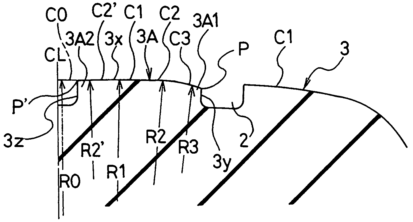
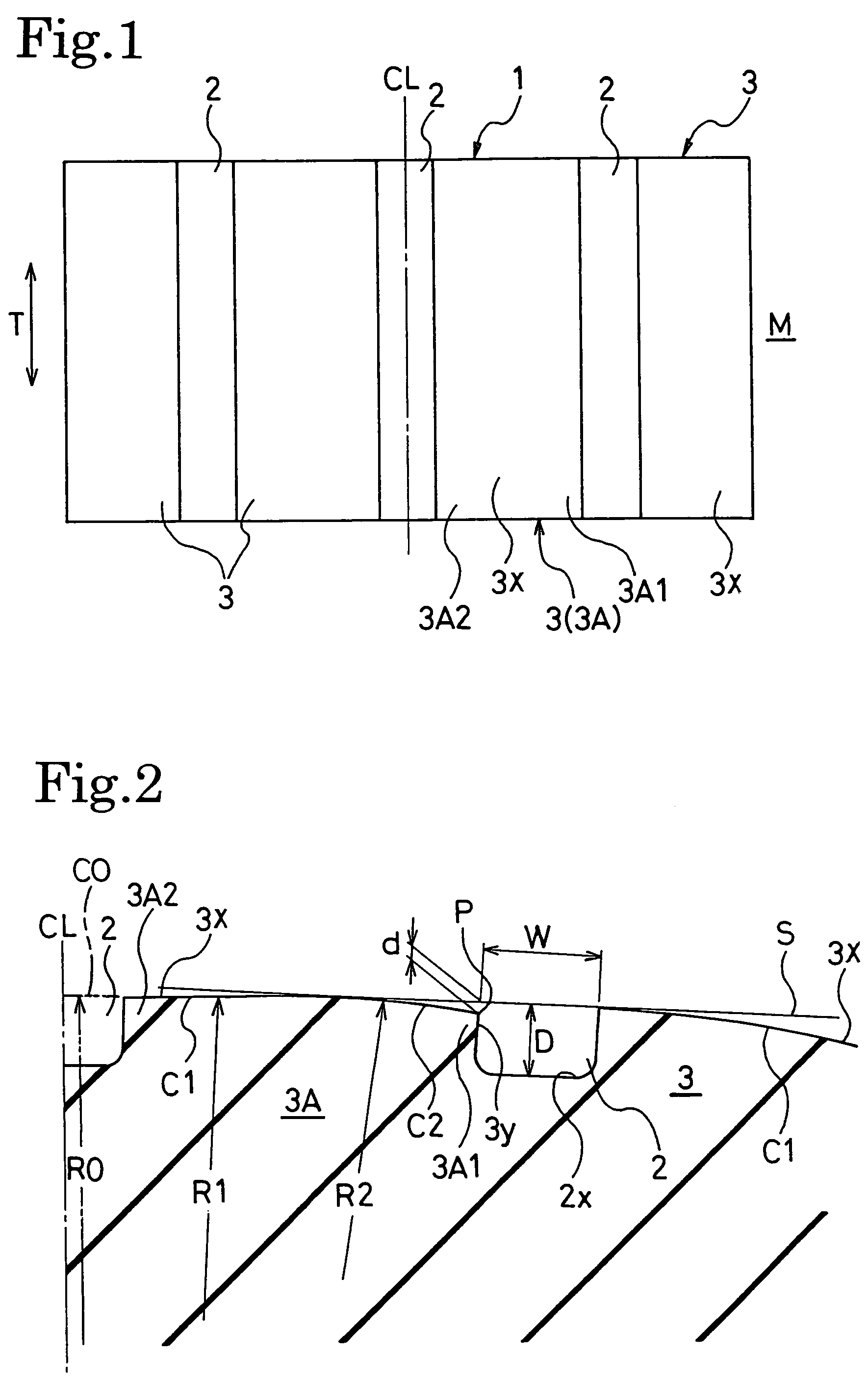
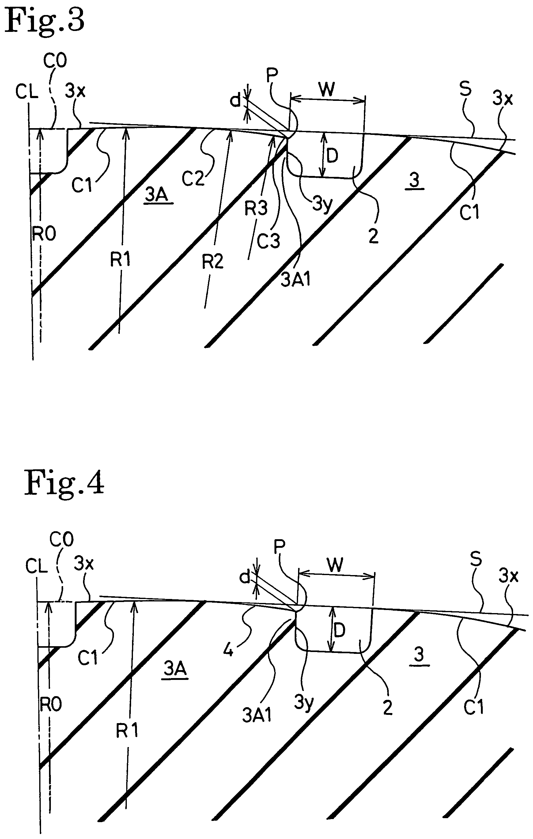
[0046]Tires 1, 2 and 3 according to the present invention were prepared, respectively, having an equal tire size of 235 / 45ZR17, the present invention tires 1 each having a tread pattern shown in FIG. 1 in which the ground contact surface of the second land portion, when counted from the outer side of a vehicle when the tire was mounted thereon, consisted of two circular arcs C1 and C2 with curvature radii R1 and R2 as shown in FIG. 2, the present invention tires 2 each having a tread pattern shown in FIG. 1 in which the ground contact surface of the second land portion consisted of three circular arcs C1, C2 and C3 with curvature radii R1, R2 and R3 as shown in FIG. 3, the present invention tires 3 each having a tread pattern shown in FIG. 1 in which the ground contact surface of the second land portion consisted of four circular arcs C1, C2, C3 and C2′ with curvature radii R1, R2, R3 and R2′ as shown in FIG. 5.

[0047]Conventional tires each having an arrangement shown in FIG. 6, and...

example 2

[0056]Test tires 1˜5 were prepared, respectively, each having the same tire size as in Example 1 and the ratio d / W of the depth d of the intersection to the groove width W of the main groove 2 shown in Table 2 in the above present invention tire 2. The curvature radii R0, R1, R2 and R3 of the circular arcs and the ratios d / D were as shown in Table 2.

[0057]Evaluation tests for turning performance and uneven wear resistance were conducted on each of the test tires as in Example 1. The results shown in Table 2 were obtained.

[0058]

TABLE 2TestTestTestTestTestTire 1Tire 2Tire 3Tire 4Tire 5R0 (mm)10001000100010001000R1 (mm)10001000100010001000R2 (mm)300300300300300R3 (mm)100100100100100d / D0.0350.0350.0350.0350.035d / W0.0080.010.100.150.16Turning103106105105103PerformanceUneven37887WearResistance

[0059]As seen in Table 2, it is understood that the ratio d / W of the depth d of the intersection to the groove width W of the main groove 2 preferably ranges from 0.01 to 0.15.

[0060]As illustrated ab...


PUM


Abstract

A pneumatic tire includes a tread surface having a plurality of main grooves extending straight in a circumferential direction of the tire. The plurality of main grooves defines land portions extending in the tire circumferential direction. The land portions each have a ground contact surface comprising a first circular are having a single curvature radius in tire meridian cross section. The ground contact surface of at least the land portion which is located second when counted from the outer side of a vehicle when the tire is mounted thereon, is arranged so as to have the first circular are and at least a second circular are connected thereto on the vehicle outer side thereof. The circular are located closer to the vehicle outer side has a smaller curvature radius and is positioned more inwardly away from the tread surface. The ratio d / D of the depth d of an intersection of the circular are located closest to the vehicle outer side with a vehicle outer sidewall surface of the at least second land portion to the groove depth D of the main groove facing to the vehicle outer sidewall surface is 0.02 to 0.1.

Description

TECHNICAL FIELD[0001]The present invention relates to pneumatic tires, and more particularly, to a pneumatic tire capable of improving uneven wear resistance and turning performance.TECHNICAL BACKGROUND[0002]Conventionally, there are pneumatic tires having a tread surface in which a plurality of main grooves extend straight in the circumferential direction of the tire to thereby define circumferentially extending ribs (land portions), and pneumatic tires having a tread surface in which, in addition to the main grooves, lateral grooves which extend in the widthwise direction of the tire are disposed in predetermined intervals in the circumferential direction of the tire to define circumferentially extending block rows (land portions) by the main grooves and lateral grooves.[0003]In such pneumatic tires, for example, as shown in FIG. 6, there is a pneumatic tire in which the ribs 13 formed between the main grooves 12 have ground contact surfaces 13x defined by a circular arc C1 in the...

Claims


Application Information

Patent Timeline
Patent Type & Authority Patents(United States)
IPC IPC(8): B60C11/00B60C3/00B60C11/04B60C11/12
CPCB60C11/0083B60C11/0309B60C11/042B60C11/1376B60C11/1384Y10S152/901B60C11/04
Inventor SHIDA, ZENICHIROU
Owner THE YOKOHAMA RUBBER CO LTD
Learn More