
Apparatus for the rapid measurement of temperatures in a hot gas flow

a technology of hot gas flow and apparatus, which is applied in the direction of heat measurement, liquid/fluent solid measurement, instruments, etc., can solve the problems of reducing the service life and the risk of damage to the first turbine stage, and achieves the effects of reducing the time constant, high reliability, and simple design

Inactive Publication Date: 2009-01-20
ANSALDO ENERGIA IP UK LTD
View PDF10 Cites 4 Cited by
  • Summary
  • Abstract
  • Description
  • Claims
  • Application Information

AI Technical Summary

Benefits of technology

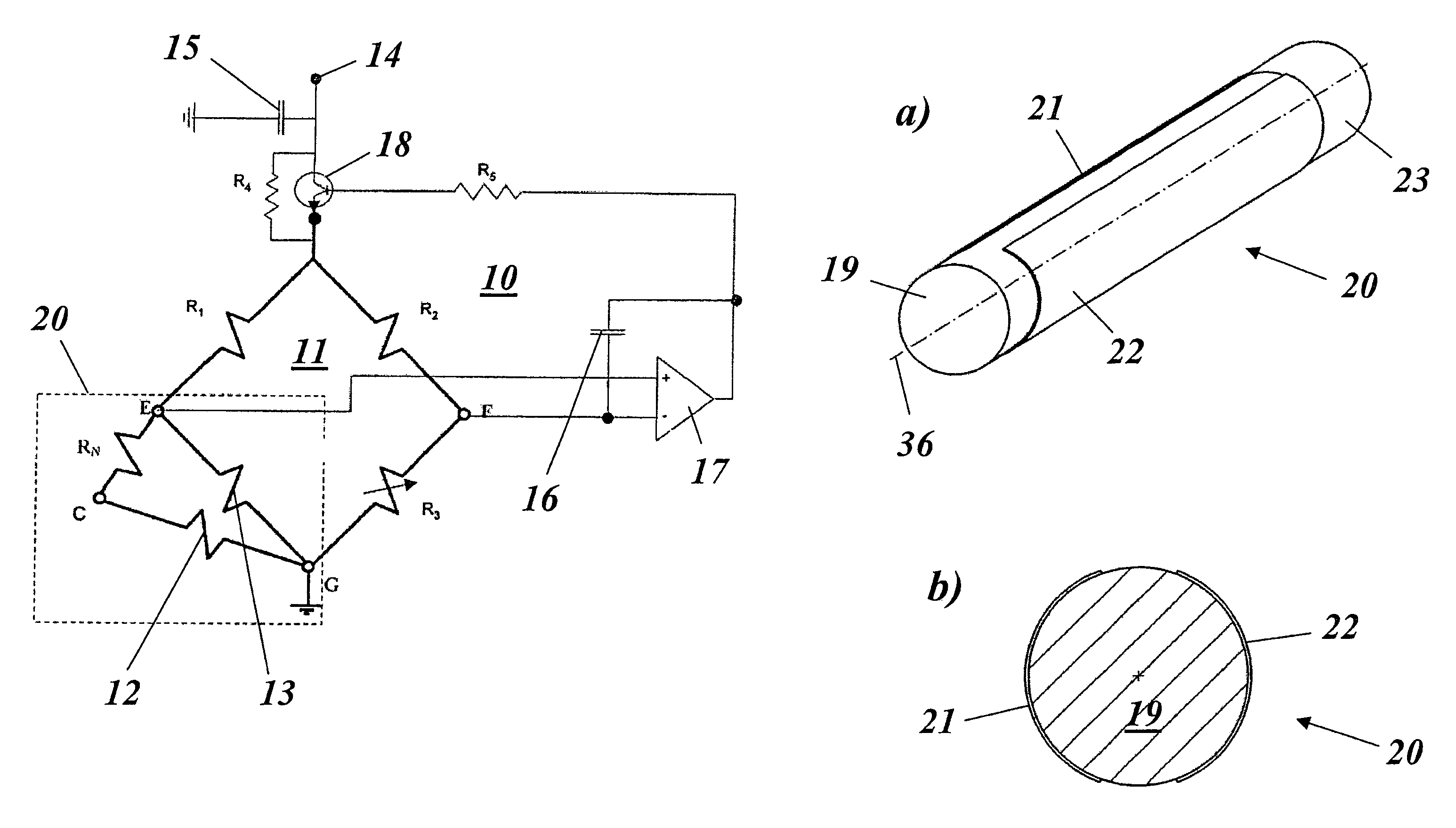
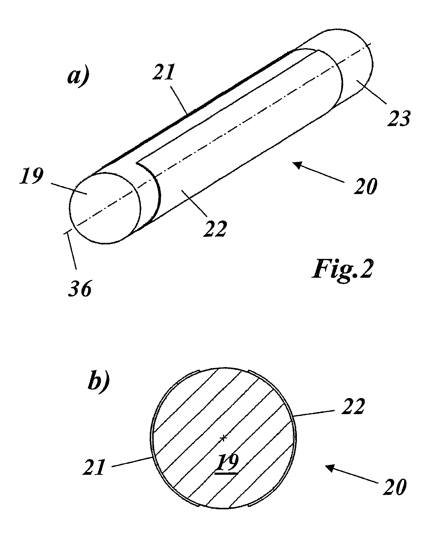
"The present invention provides an apparatus for measuring temperatures in a hot gas flow, such as in a gas turbine, with a reduced time constant, high reliability, simple design, good accuracy, and flexible applicability. The apparatus includes a sensor with two two-dimensional, electrically conductive heating elements attached to the surface of a common sensor body. The heating elements are heated to different temperatures and the resistance in the sensor body is kept constant by a closed-loop control circuit. The gas temperature can then be determined by a linear equation of the ratio of the voltage drops across the colder heating element and the connecting resistor. The sensor body is cylindrical and the heating elements are arranged on opposite sides of the cylinder surface in relation to the axis. The heating elements are electrically conductively connected to one another at one end. The sensor is surrounded concentrically by a radiation shield which forms an annular channel through which the gas passes. The electrical circuit is further simplified by the radiation shield being electrically conductive and being electrically conductively connected to the sensor head for grounding the sensor head. The sensor can be fixed to a base body by closing one end of the annular channel and providing outlet openings in the radiation shield at the other end. The heating elements are conductively connected to one another directly and via a first resistor in a circuit arrangement that keeps the resistance in the measurement branch constant. The measurement bridge is preferably part of a circuit arrangement that keeps the resistance in the branch constant using a closed-loop control circuit."

Problems solved by technology

This results in the risk of damage to the first turbine stages since the thermocouples cannot detect a thermal overload with the required speed.
Furthermore, in the case of measured value pick-ups based on thermocouples, any attempt at increasing the time response results, without exception, in a reduction in the service life.

Method used


Image

  • Apparatus for the rapid measurement of temperatures in a hot gas flow
  • Apparatus for the rapid measurement of temperatures in a hot gas flow
  • Apparatus for the rapid measurement of temperatures in a hot gas flow

Examples


Embodiment Construction

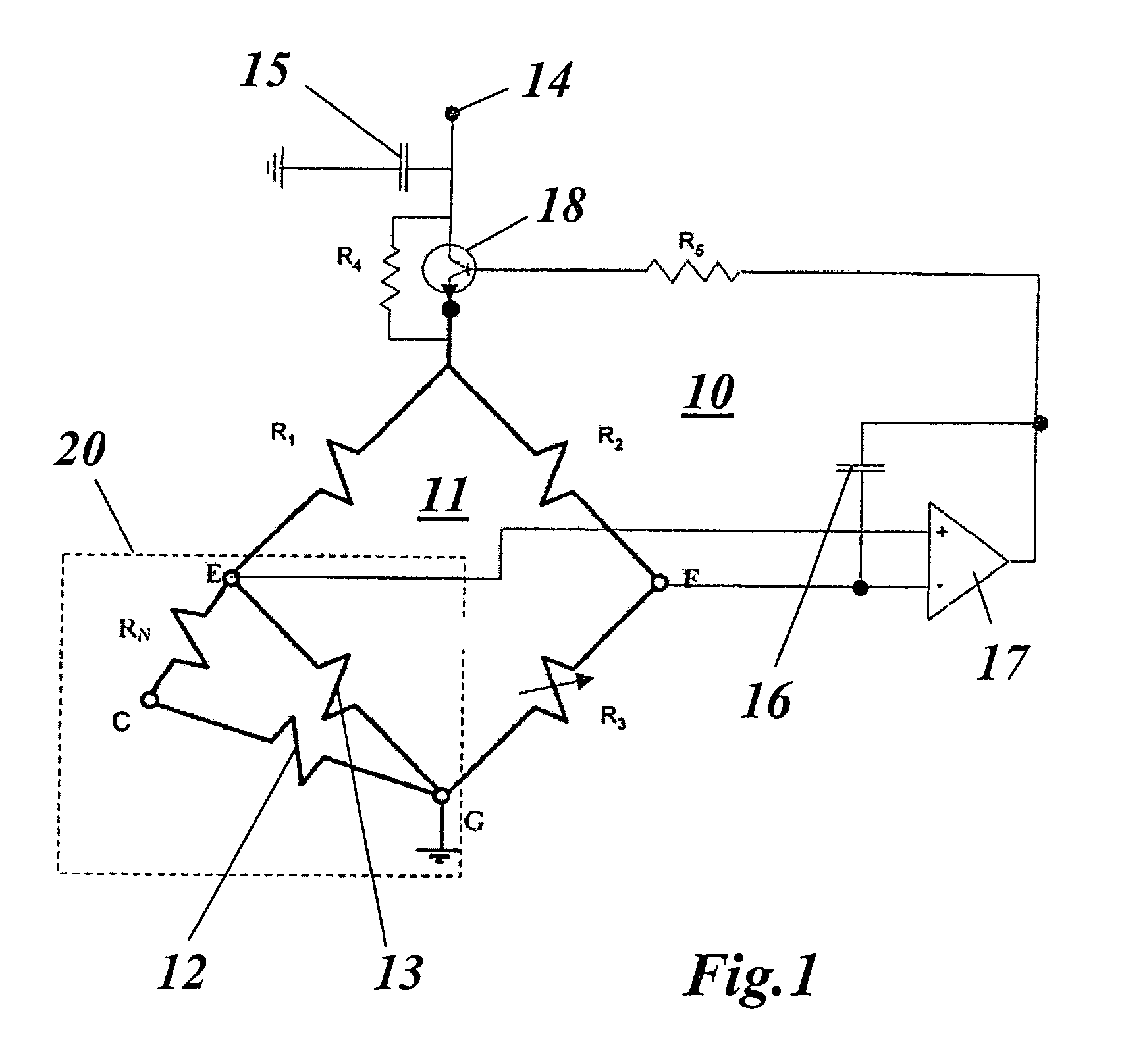
[0019]FIG. 1 depicts a circuit arrangement or measuring circuit 10, which is known per se from U.S. Pat. No. 6,609,412 and can be used in conjunction with the sensor according to the invention for the purpose of measuring the hot gas temperature, in particular in a gas turbine. The circuit arrangement 10 comprises a measurement bridge having four bridge branches, of which three are formed by the resistors R1, R2 and R3. The resistor R3 is designed such that it can be adjusted so as to match the bridge. The fourth bridge branch is formed by two heating elements 12 and 13, which are connected to one another directly at one end and via a further resistor RN at the other end. The point G of the measurement bridge 11, at which the two heating elements 12, 13 are connected to one another directly, is connected to ground. The point, which lies diagonally opposite the point G, of the measurement bridge 11 is connected to a supply connection 14 via the collector / emitter path of a transistor ...


PUM


Abstract

An apparatus for a rapid measurement of temperatures in a hot gas flow, in particular in a gas turbine. The apparatus includes a sensor having two two-dimensional, electrically conductive heating elements, which are attached to the surface of a common, electrically insulating sensor body.

Description

[0001]Priority is claimed to Swiss Patent Application No. CH 01758 / 04, filed on Oct. 25, 2004, the entire disclosure of which is incorporated by reference herein.[0002]The present invention relates to the field of temperature measurement technology. It relates to an apparatus for the rapid measurement of temperatures in a hot gas flow.BACKGROUND[0003]It is of central importance in a gas turbine to determine the temperature distribution in the hot gas flow at the turbine outlet, since the efficiency of the overall gas turbine is influenced by this temperature distribution. In particular, this temperature distribution is critical for improving the design of the turbine and for controlling the turbine operation. In particular in relation to turbine control, it is known that the time constant of the TOT measured value pick-up (TOT=Turbine Outlet Temperature), which is currently in use and operates using thermocouples, is greater than one second (approximately 3 s), while the time consta...

Claims


Application Information

Patent Timeline
Patent Type & Authority Patents(United States)
IPC IPC(8): G01F1/68
CPCG01K7/42G01K13/02
Inventor RUFFINO, PAOLOZINN, HANSPETER
Owner ANSALDO ENERGIA IP UK LTD
Learn More