
Dual sided board thermal management system

a thermal management system and dual-sided board technology, applied in the direction of electrical equipment construction details, lighting and heating equipment, domestic cooling equipment, etc., can solve the problems that conventional dry thermal management technology, air convection using fans and heat sinks, etc., are not efficient thermal management of modern electronics, and achieve efficient thermal management

Active Publication Date: 2009-01-13
PARKER INTANGIBLES LLC
View PDF29 Cites 70 Cited by
  • Summary
  • Abstract
  • Description
  • Claims
  • Application Information

AI Technical Summary

Benefits of technology

[0014]An object is to provide a dual sided board thermal management system for efficiently thermally managing a printed circuit board having electronic components on opposing sides thereof.

Problems solved by technology

Conventional dry thermal management technology (e.g. forced air convection using fans and heat sinks) simply is not capable of efficiently thermally managing modern electronics.

Method used


Image

  • Dual sided board thermal management system
  • Dual sided board thermal management system
  • Dual sided board thermal management system

Examples


Embodiment Construction

A. Overview

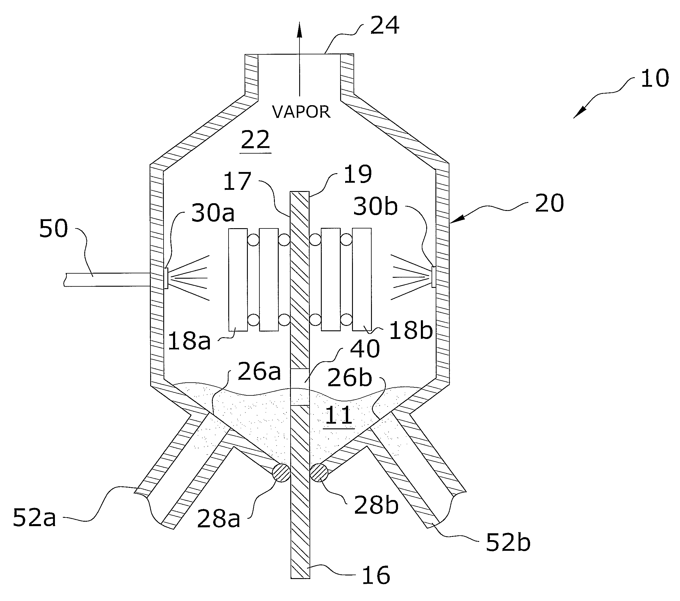
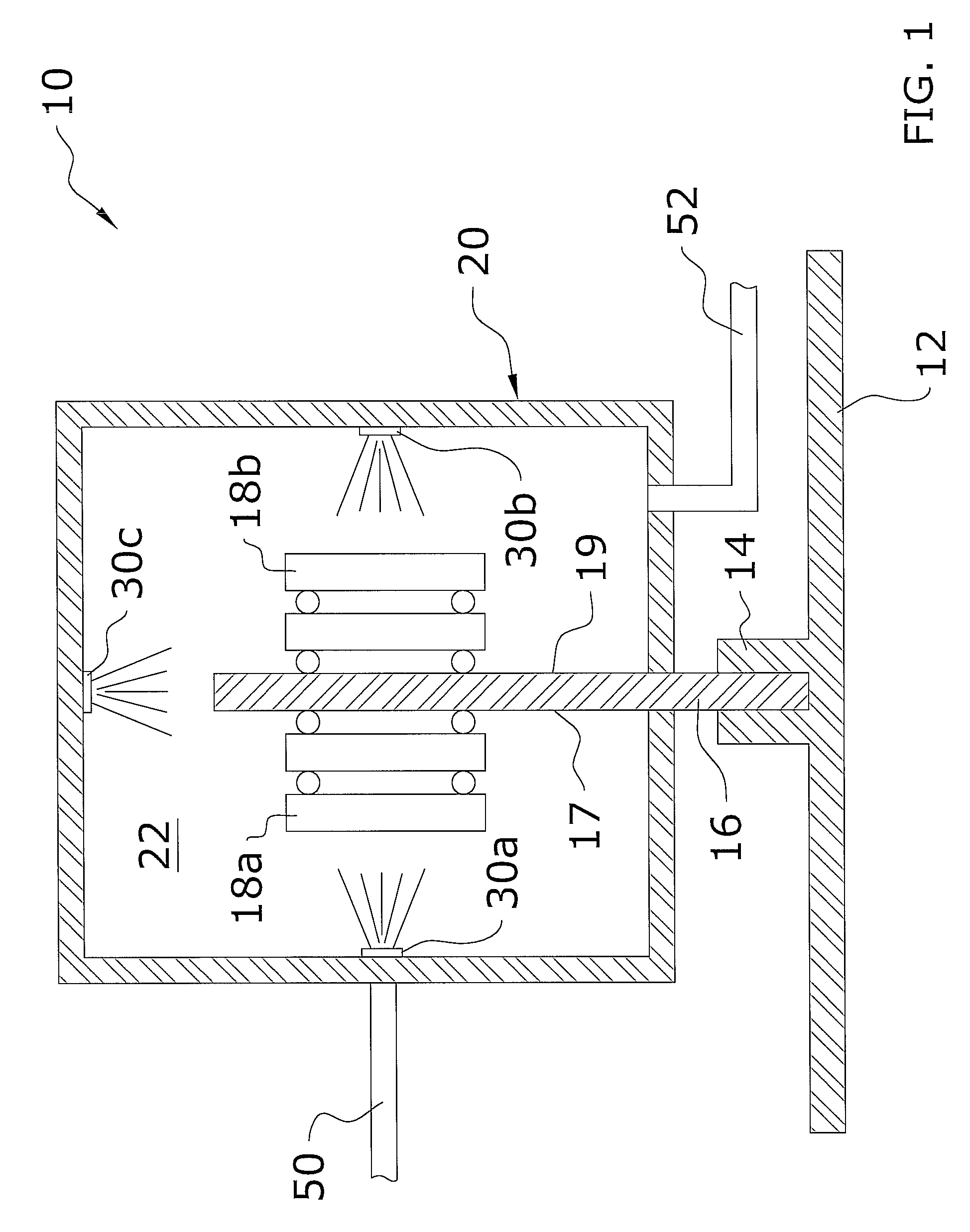
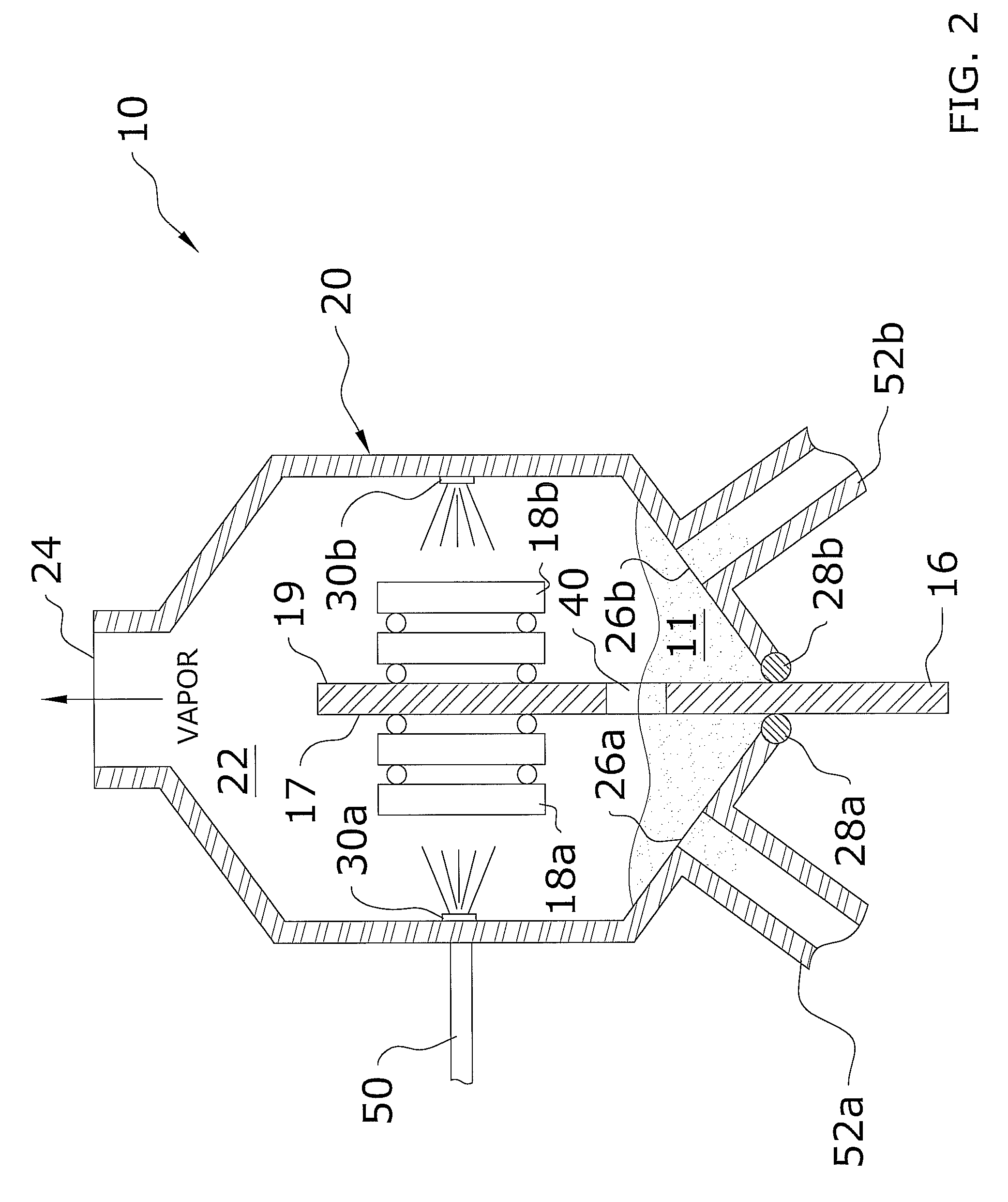
[0023]Turning now descriptively to the drawings, in which similar reference characters denote similar elements throughout the several views, FIGS. 1 through 5 illustrate a dual sided board thermal management system 10, which comprises a housing 20 surrounding a portion of a printed circuit board 16, and a plurality of spray units 30a, 30b, 30c within the housing 20 directed towards opposite sides of the printed circuit board 16 to thermally manage electronic components 18a, 18b on opposite sides of the printed circuit board 16.

B. Printed Circuit Board

[0024]FIGS. 1 through 4 illustrate a printed circuit board 16 suitable for use in the present invention. The printed circuit board 16 may be comprised of various types of circuit boards such as but not limited to expansion boards, dual in-line memory modules (DIMM), controller boards, network interface cards, video adapters, motherboards and daughter cards.

[0025]The first side 17 of the printed circuit board 16 includes at le...


PUM


Abstract

A dual sided board thermal management system for efficiently thermally managing a printed circuit board having electronic components on opposing sides thereof. The dual sided board thermal management system generally includes a housing surrounding a portion of a printed circuit board, and a plurality of coolant dispensing units within the housing directed towards opposite sides of the printed circuit board to thermally manage electronic components on opposite sides of the printed circuit board.

Description

CROSS REFERENCE TO RELATED APPLICATIONS[0001]Not applicable to this application.STATEMENT REGARDING FEDERALLY SPONSORED RESEARCH OR DEVELOPMENT[0002]Not applicable to this application.BACKGROUND OF THE INVENTION[0003]1. Field of the Invention[0004]The present invention relates generally to liquid thermal management devices and more specifically it relates to a dual sided board thermal management system for efficiently thermally managing a printed circuit board having electronic components on opposing sides thereof.[0005]2. Description of the Related Art[0006]Any discussion of the prior art throughout the specification should in no way be considered as an admission that such prior art is widely known or forms part of common general knowledge in the field.[0007]Modern electronic devices (e.g. integrated circuits, microprocessors, circuit boards and power supplies) and other heat producing devices have significant thermal management requirements. Conventional dry thermal management tec...

Claims


Application Information

Patent Timeline
IPC IPC(8): H05K7/20H01L23/36
CPCH01L23/4735H05K7/20345H05K1/0272H01L2224/16145H01L2224/16
Inventor CADER, TAHIRKNIGHT, PAUL A.
Owner PARKER INTANGIBLES LLC
Learn More