Method and device for examining a sealing surface of a container mouth

a technology of sealing surface and container, which is applied in the direction of instrumentation, structural/machine measurement, sorting, etc., can solve the problems of series of defects in the sealing surface of the bottle mouth, a risk for consumers drinking from the bottle, and the sealing surface includes nicks, orange peel or even other defects, so as to achieve a wide range of contrast

Inactive Publication Date: 2009-01-13
HEYE INT
View PDF26 Cites 15 Cited by
  • Summary
  • Abstract
  • Description
  • Claims
  • Application Information

AI Technical Summary

Benefits of technology

[0019]It is the object of the invention to provide a generic method of examining a container mouth which using simple means renders it possible to amplify contrast during the detection of defects in the mouth sealing surface. It is also the object of the invention to provide a generic device which is suitable for carrying out this method.

Problems solved by technology

During the production of glass bottles, a series of defects can be produced in the sealing surface of the bottle mouth.
Other possible flaws in the sealing surface include nicks, orange peel or even other defects.
Cracks in the sealing region of a drinks bottle can be the starting point of localized breakage of the mouth lip and thus represent a risk for a consumer drinking from the bottle.
A problem which arises in practical usage resides in the fact that the intensity of the reflection rings 28, 29 is generally considerably greater than the intensity of the light 33 which passes into the camera 18 by reason of a defect in the sealing surface 3.
A disadvantage of this shield is that defects cannot be detected in the shielded mouth regions.
In order to achieve the desired degree of shielding, relatively complex light-guiding devices are required, e.g. an annular element having tangentially aligned holes or light-guiding plates.
Moreover, a disadvantage of the known testing device is that it is not achieved to uniformly illuminate the sealing surface which is to be examined and light intensity on the whole is lost by virtue of the shielding arrangement.
It is also not possible to achieve a tangential deflection simultaneously on both sides using the described light-guiding devices.

Method used


Image

  • Method and device for examining a sealing surface of a container mouth
  • Method and device for examining a sealing surface of a container mouth
  • Method and device for examining a sealing surface of a container mouth

Examples


Embodiment Construction

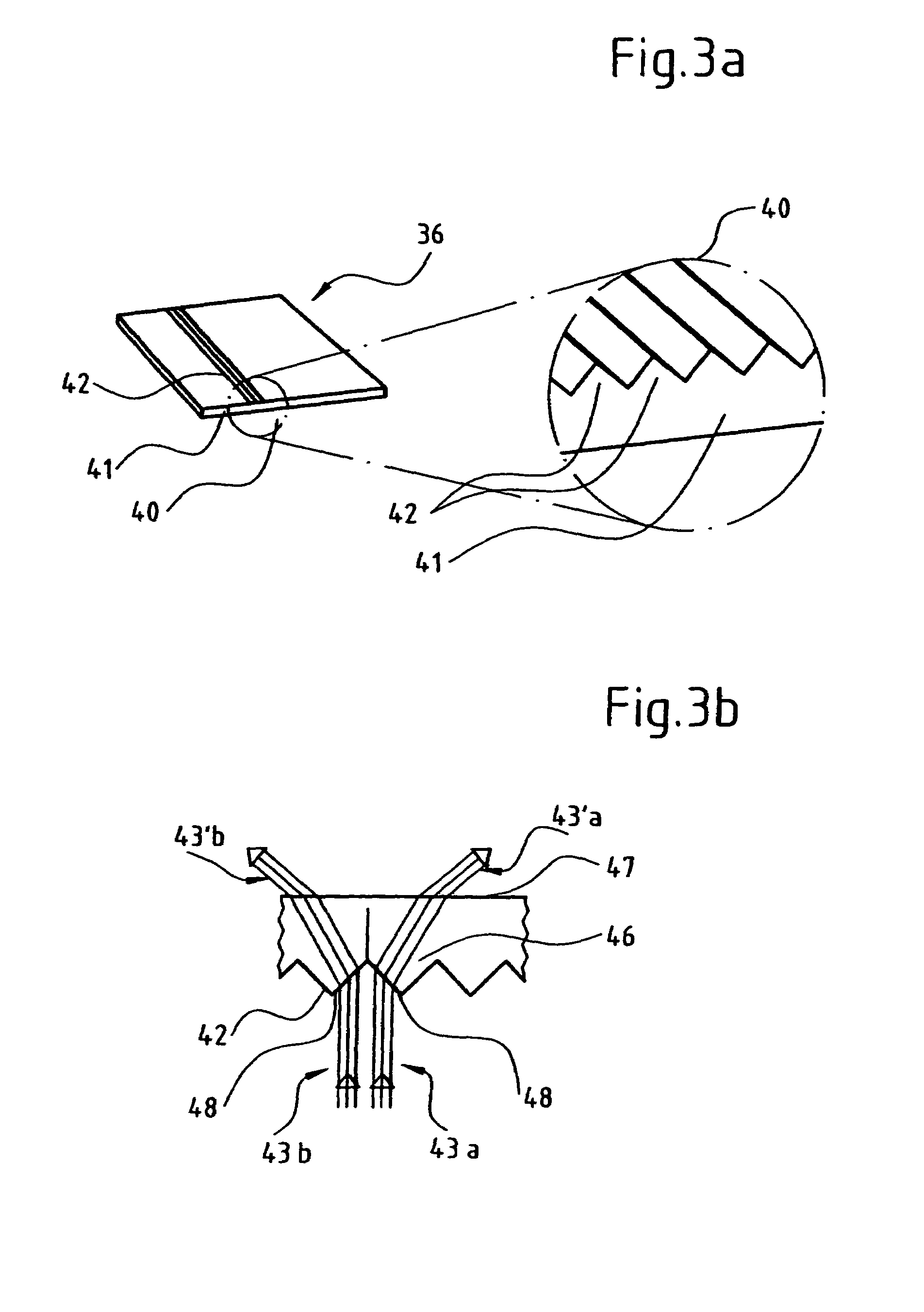
[0050]FIG. 3a illustrates a line splitter film 36, as can be used as a component of an optical deflecting element 38 or 39 described hereinunder. As shown in particular in an enlarged section 40, the line splitter film 36 comprises a planar base 41. One side of the base 41 is occupied completely by parallel prism strips 42 (not all of which are illustrated) which directly adjoin one another. The prism strips 42 are elongated prisms consisting of translucent material. As shown in FIG. 3b, light beams which are aligned perpendicularly with a smooth underside 47 of the line splitter film 36 and impinge upon lateral surfaces 48 of the prism strips 42 are broken. The broken light beams pass through the prism base 46 to the smooth underside 47 of the line splitter film 36 and are broken once again at this location. By reason of the effect of the corresponding prism strip 42 the light beams 43a produce the light beams 43′a and the light beams 43b produce the light beams 43′b. In FIG. 3b, l...


PUM

PropertyMeasurementUnit
reflected beam opening angleaaaaaaaaaa
angleaaaaaaaaaa
transparentaaaaaaaaaa

Abstract

The invention concerns a method and a device for examining a container mouth for defects in a mouth sealing surface. A light source emits light beams having a direction component impinging tangentially upon the sealing surface. The tangential light beams are scattered as they impinge upon a defect in the sealing surface. At least some of these scattered light beams are detected by a sensor. The tangential direction component is produced by an optical deflecting element disposed between the light source and the mouth. The optical deflecting element is transparent at least to light of certain wavelengths and deflects impinging light beams accordingly. The invention renders it possible to amplify contrasts between defects and other reflections from the sealing surface during the detection of defects in the sealing surface.

Description

FIELD OF THE INVENTION[0001]The invention relates to a method and a device for detecting defects in the sealing surface of a mouth of a container.[0002]In particular, the container can be a glass bottle or a wide-necked glass. In particular, the mouth can be a mouth for closing the container by means of a crown cork or a screw mouth.BACKGROUND OF THE INVENTION[0003]During the production of glass bottles, a series of defects can be produced in the sealing surface of the bottle mouth. In order to ensure that the sealing surface can cooperate in a problem-free manner with the closure element provided and in particular leakages are obviated, it is important to detect wrinkles extending e.g. radially over the mouth surface and to separate out the corresponding containers. Other possible flaws in the sealing surface include nicks, orange peel or even other defects. Cracks in the sealing region of a drinks bottle can be the starting point of localized breakage of the mouth lip and thus rep...

Claims


Application Information

Patent Timeline
Patent Type & Authority Patents(United States)
IPC IPC(8): G01N21/00G01M99/00
CPCB07C5/3408G01N21/9054
Inventor SCHMIDT, PETERSTUWE, HARTWIN
Owner HEYE INT
Why Eureka
Try Eureka