High mobility vehicle

a high-mobility vehicle and high-speed technology, applied in vehicles, manipulators, manufacturing tools, etc., can solve the problems of human health hazards in operating scenarios, and achieve the effects of reducing rolling losses, extending the operating life of platforms, and reducing rolling losses

Inactive Publication Date: 2009-01-13
DEROOS BRADLEY G
View PDF19 Cites 122 Cited by
  • Summary
  • Abstract
  • Description
  • Claims
  • Application Information

AI Technical Summary

Benefits of technology

[0005]Manned and remotely controlled vehicles must often be able to provide a high degree of mobility in a wide range of operating environments. A high-mobility vehicle is described which offers enhanced maneuverability and control while operating in diverse environments including, but not limited to: gravel and finished road surfaces; rugged, off-road operating areas; and, urban environments, both inside and outside of buildings. The high-mobility vehicle described herein includes two forward end and two rearward end arm and wheel assemblies and two track assemblies. The arm and wheel assemblies have wheels mounted at the outer end of each arm, and have inner ends which are pivotally mounted on the vehicle chassis. The forward and rearward arm and wheel assemblies can be downwardly deployed, thereby raising the vehicle track assemblies off of the driving surface, thereby allowing the vehicle to maneuver without utilizing the track assemblies. Pivoting the arm and wheel assemblies downward to lift the chassis and track assemblies would most often be performed in those situations where the traction provided by the wheel assemblies is sufficient for vehicle locomotion. Additionally, the arm and wheel assemblies can be pivoted upward to a position past vertical. This results in vehicle footprint reduction which serves to enhance maneuverability in constrained operating environments. The high-mobility vehicle described is equipped with a power transmission mechanism that provides high and low gear ratios. The power transmission mechanism creates a high-torque, low-speed mode of operation when the vehicle is using the track assemblies for locomotion and steering, and a low-torque, high-speed mode of operation when the vehicle is using the wheel assemblies for locomotion and steering.
[0006]One or two movable pairs of arm and wheel assemblies are provided on a high-mobility vehicle that can alternately be driven by wheels located at the end of arm and wheel assemblies, or by track assemblies. The arm and wheel assemblies pivot about points at the rearward and forward ends of the vehicle chassis, thereby allowing the operator to downwardly rotate the arm and wheel assemblies to lift the track assemblies off of the ground, or upwardly rotate the arm and wheel assemblies to establish a reduced vehicle footprint.
[0009]Utilizing wheels as a means of locomotion reduces rolling losses as compared to the rolling losses associated with tracked vehicles. Reduction of rolling losses extends the operating life of a platform that relies on a self-contained power source as the basis for locomotion. There are advantages to being able to alter or reconfigure locomotive means on a given platform between wheeled locomotion and tracked locomotion. Mobility, maneuverability, speed and mechanical efficiency are all affected by the locomotive means selected. The combination of tracks and wheels can provide a vehicle in which vibrations are decreased when running, which has greater stability in rough terrain and on stairs, and which has increased vehicle speed compared to a track-only design.
[0010]Accordingly, it is an object of the present invention to provide a vehicle that has high-mobility in a wide range of operating environments, which has a footprint that can be modified to allow operation in space-constrained environments, and which provides the ability to effectively and efficiently transition from a high-speed, low-torque mode of operation to a low-speed, high-torque mode of operation.

Problems solved by technology

Some operating scenarios are hazardous to humans which may necessitate the use of a high-mobility remotely controlled vehicle.

Method used


Image

  • High mobility vehicle
  • High mobility vehicle
  • High mobility vehicle

Examples


Embodiment Construction

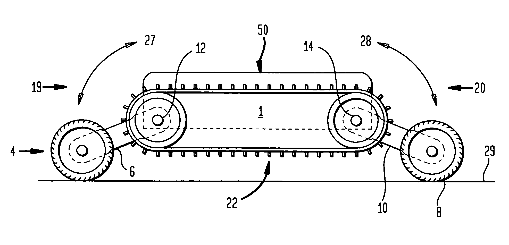
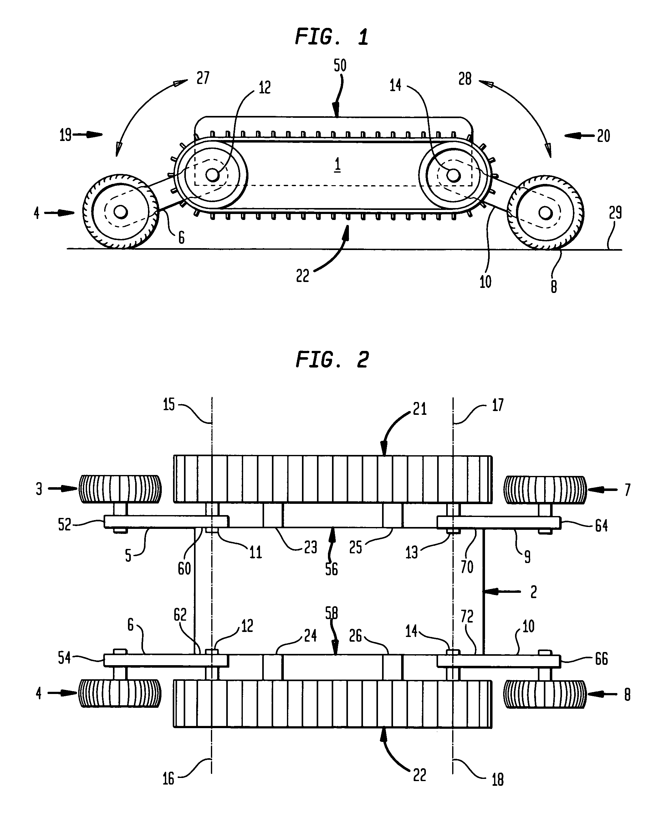
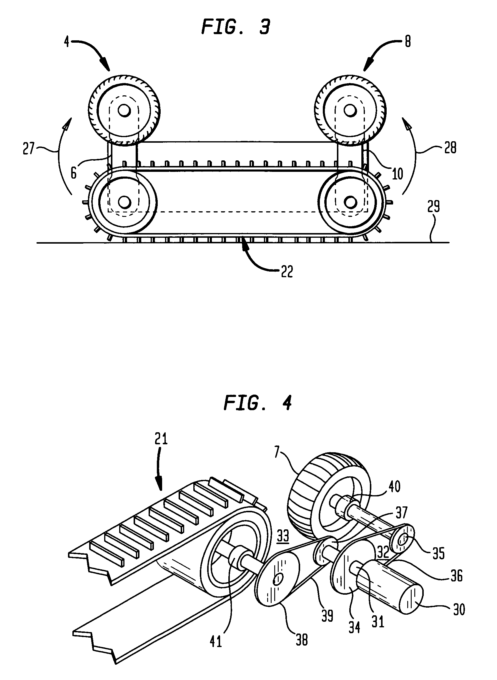
[0021]FIGS. 1-3 illustrate a high-mobility vehicle 1 which includes a vehicle body 50 comprising a chassis 2. The vehicle body 50 has a front portion 19, a rear portion 20, a right side 56, and a left side 58. Front trackless drive wheels 3, 4 are mounted at the distal ends 52, 54 of front arms 5, 6. The proximal ends 60, 62 of the front arms 5, 6 are pivotally mounted on the chassis 2 with pivot mounts 11, 12. Similarly, rear trackless drive wheels 7, 8 are mounted at the distal end 64, 66 of rear arms 9, 10. The proximal ends 70, 72 of the rear arms 9, 10 are pivotally mounted on the chassis 2 with pivot mounts 13, 14. The front arm and trackless drive wheel assemblies rotate about axis 15-16, and the rear arm and trackless drive wheel assemblies rotate about axis 17-18. The front and rear arms 5, 6, 9, 10 are configured such that the trackless drive wheels 3, 4, 7, 8 can pivotally rotate 27, 28 while remaining clear of right and left track assemblies 21, 22. The track assemblies ...


PUM


Abstract

An embodiment of a high-mobility vehicle comprises a vehicle body, a track assembly attached to the vehicle body, arms pivotally attached to the vehicle body, and trackless drive wheels mounted on distal ends of the arms. Another embodiment of a high-mobility vehicle comprises a vehicle chassis, right and left drive motors attached to the vehicle chassis, right and left power transmission mechanisms having high torque and low torque sets of gears, track assemblies coupled to the high torque sets of gears, and trackless drive wheels coupled to the low torque sets of gears.

Description

BACKGROUND[0001]1. Field of the Invention[0002]The present invention relates to a high-mobility vehicle which can effectively traverse and maneuver within a wide range of naturally occurring and man-made operating environments. When operated as a remotely controlled system, the high-mobility vehicle can help to ensure the safety of an operator in hazardous environments such as bomb disposal, disaster relief, and response to chemical, biological, radiological, or nuclear events.[0003]2. Description of Related Art[0004]There are many working and operating environments that require a vehicle with a high degree of mobility in order to accomplish specific operational objectives. Some operating scenarios are hazardous to humans which may necessitate the use of a high-mobility remotely controlled vehicle. Examples where a high-mobility remotely controlled vehicle would be advantageous include bomb disposal, mine clearance and neutralization, surveillance, environmental remediation, work in...

Claims


Application Information

Patent Timeline
IPC IPC(8): B62D55/02
CPCB62D55/02B62D55/075B25J11/0025
Inventor DEROOS, BRADLEY G.
Owner DEROOS BRADLEY G
Why Eureka
Try Eureka