
Apparatus and methods for creation of down hole annular barrier

a technology of annular barrier and well bore, which is applied in the direction of sealing/packing, borehole/well accessories, survey, etc., can solve the problems of not preventing, cave-in or well bore fluid control becoming potential problems, and operations requiring cessation of drilling operations, so as to add redundancy to the fluid barrier seal mechanism

Inactive Publication Date: 2009-01-13
WEATHERFORD TECH HLDG LLC
View PDF107 Cites 15 Cited by
  • Summary
  • Abstract
  • Description
  • Claims
  • Application Information

AI Technical Summary

Benefits of technology

The invention is about a method and apparatus for performing a shoe test in a well bore using an expandable casing portion as an annular fluid barrier. The expandable casing portion can be used with or without cement. The method involves lowering a casing or liner string into the well bore, where the string includes a non-circular or folded expandable portion at the lower end. The folded expandable portion is designed to expand and seal with the well bore when pressure is applied. The method also includes steps for retrieving the folded expandable portion and performing a second shoe test if the first test fails. The technical effect of the invention is to provide a reliable and efficient method for performing a shoe test in a well bore.

Problems solved by technology

Initially a hole is drilled in the earth to a depth at which earth cave-in or well bore fluid control become potential issues.
While the casing may structurally prevent cave-in, it will not prevent fluid migration along a length of the well in the annulus between the casing and the well bore.
Unfortunately cementing operations require cessation of drilling operations for considerable periods of time.
It takes time to mix and pump the cement.
It takes more time to allow the cement to cure once it is in place.
During the cementing operations drilling rig costs and other fixed costs still accrue yet no drilling progress is made.
Regardless of whether or not the cross-section is initially circular or is folded, expandable pipe has limitations of expandability based on the expansion mechanism chosen.
If the chosen expansion mechanism is miscalculated in a given circumstance the result can be extremely disadvantageous.
In that situation the expanded pipe is not useful as a barrier and further, because the pipe has been expanded retrieval may be impractical.
Remedying such a situation consumes valuable rig time and accrues other costs associated with remediation equipment and replacement of the failed expandable pipe.

Method used


Image

  • Apparatus and methods for creation of down hole annular barrier
  • Apparatus and methods for creation of down hole annular barrier
  • Apparatus and methods for creation of down hole annular barrier

Examples


Embodiment Construction

[0024]The invention generally relates to methods and apparatus for creating an annular barrier about a casing shoe.

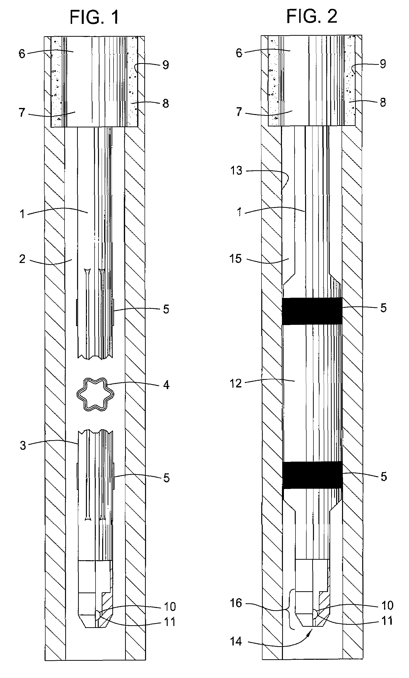
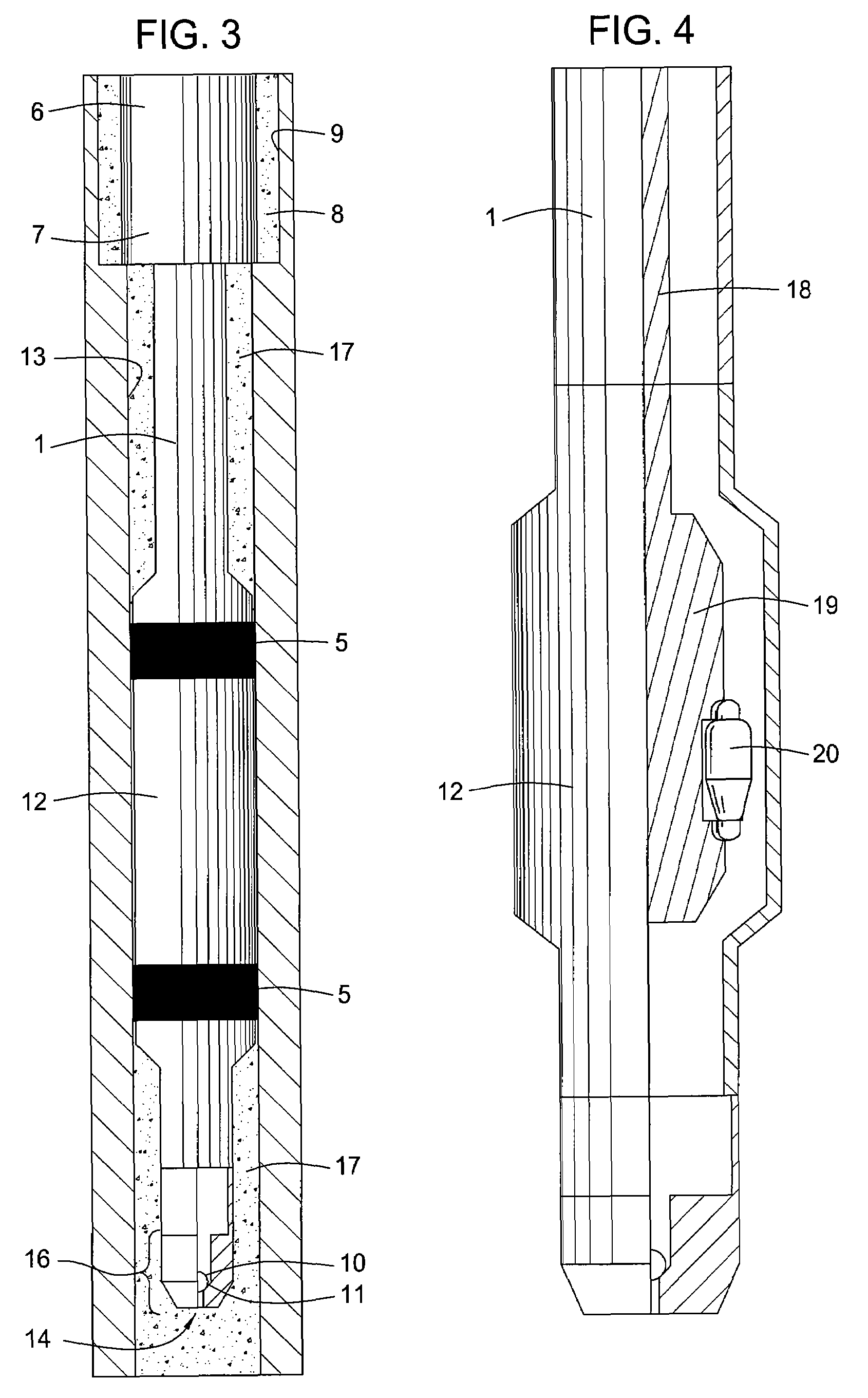
[0025]The embodiments of FIGS. 1, 2 and 3 are shown deployed beneath a previously and conventionally installed casing 6 in a previously drilled well bore 9. The annular barrier between the conventional shoe portion 7 of the previously installed casing 6 and the previously drilled well bore 9 is only cement 8.

[0026]FIG. 1 shows a casing string 1 deployed in a sectioned well bore 2 where the casing string 1 includes an unexpanded folded expandable portion 3 and a cross-section thereof 4 and having two elastomeric coated regions 5 about a perimeter of the folded portion 3. The well bore 2 is drilled following the drilling of the well bore 9, running of the casing 6, placing of the cement 8 and shoe testing the barrier formed by the cement 8. The casing string 1 is lowered from the surface into the well bore 2 and a ball 10 is placed in the interior of the casing 1 and allo...


PUM


Abstract

Methods and apparatus are provided for performing an expedited shoe test using an expandable casing portion as an annular fluid barrier. Such an expandable annular fluid barrier may be used in conjunction with cement if so desired but cement is not required. Further provided are methods and apparatus for successfully recovering from a failed expansion so that a shoe test can be completed without replacement of the expandable casing portion.

Description

CROSS-REFERENCE TO RELATED APPLICATION[0001]This application claims benefit of U.S. Provisional Patent Application Ser. No. 60 / 701,720, filed on Jul. 22, 2005, which application is incorporated herein by reference in its entirety.BACKGROUND OF THE INVENTION[0002]1. Field of the Invention[0003]Embodiments of the invention generally relate to methods and apparatus for creating an annular barrier in a well bore. More particularly, the invention relates to methods and apparatus for isolating at least a portion of a well bore from at least another portion of the well bore.[0004]2. Description of the Related Art[0005]As part of the well bore construction process, a hole or well bore is typically drilled into the earth and then lined with a casing or liner. Sections of casing or liner are threaded together or otherwise connected as they are run into the well bore to form what is referred to as a “string.” Such casing typically comprises a steel tubular good or “pipe” having an outer diamet...

Claims


Application Information

Patent Timeline
Patent Type & Authority Patents(United States)
IPC IPC(8): E21B23/00
CPCE21B33/128E21B43/103E21B47/0005E21B47/005E21B21/10E21B29/00
Inventor RING, LEVCOOK, ROBERT LANCE
Owner WEATHERFORD TECH HLDG LLC
Learn More