Method for synchronizing memory areas in a transmitter apparatus and a receiver apparatus, and receiver apparatus

a technology of synchronizing memory and transmitter, applied in the direction of data switching networks, duplex signal operation, digital transmission, etc., can solve the problem of preventing correct synchronization of transmitter memory area and receiver memory area

Active Publication Date: 2008-12-23
MAGNOLIA LICENSING LLC
View PDF4 Cites 1 Cited by
  • Summary
  • Abstract
  • Description
  • Claims
  • Application Information

AI Technical Summary

Benefits of technology

[0009]The invention is based on the object of specifying an improved method for synchronizing a transmitter memory area in a transmitter apparatus with a receiver memory area in a receiver apparatus and a receiver apparatus which prevent incorrect synchronization.
[0017]A fundamental advantage which the invention achieves over the prior art is that the method is used to ensure reliable synchronization between the transmitter memory area and the receiver memory area by virtue of the reference identification for the feedback message being imperatively derived from the identification for a received-data packet, which identification is error-free. Using the method, this absence of error is also ensured when, previously, when transmitting the current reference received-data packet, an error has occurred which has resulted in an incorrect identification in the current reference received-data packet. However, ascertaining an error-free identification in a received-data packet which has been transmitted without error and subsequently ascertaining the correct identification for the current reference received-data packet prevents the incorrect identification from being used to derive the reference identification for the feedback message. The incorrect identification is automatically replaced with the correct identification in the method in order to derive the reference identification.
[0018]This improves the overall security of the data transmission in a network to which the transmitter apparatus and the receiver apparatus are connected. Transmission errors are prevented from resulting in disadvantageous subsequent errors in the network.

Problems solved by technology

However, this procedure has the problem that the reference identification for the feedback message is sometimes derived on the basis of the sequence number of a received-data packet which has itself been transmitted incorrectly between the transmitter apparatus and the receiver apparatus, which prevents correct synchronization of the transmitter memory area and the receiver memory area.

Method used


Image

  • Method for synchronizing memory areas in a transmitter apparatus and a receiver apparatus, and receiver apparatus
  • Method for synchronizing memory areas in a transmitter apparatus and a receiver apparatus, and receiver apparatus
  • Method for synchronizing memory areas in a transmitter apparatus and a receiver apparatus, and receiver apparatus

Examples


Embodiment Construction

[0009]The invention is based on the object of specifying an improved method for synchronizing a transmitter memory area in a transmitter apparatus with a receiver memory area in a receiver apparatus and a receiver apparatus which prevent incorrect synchronization.

[0010]The invention is achieved by a method having the features specified in claim 1 and by a receiver apparatus having the features specified in claim 7.

[0011]Advantageous Developments are Presented in the Subclaims.

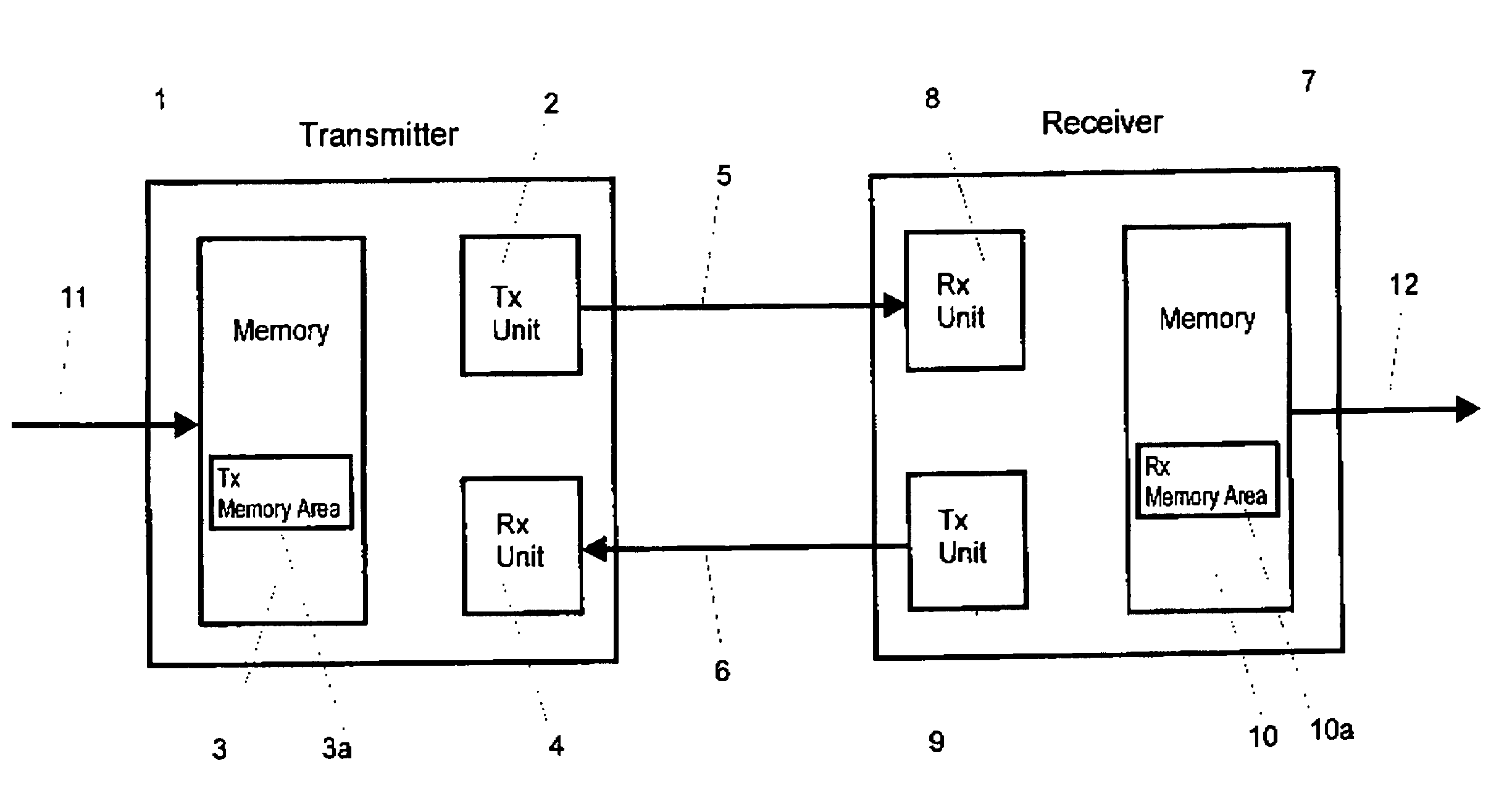
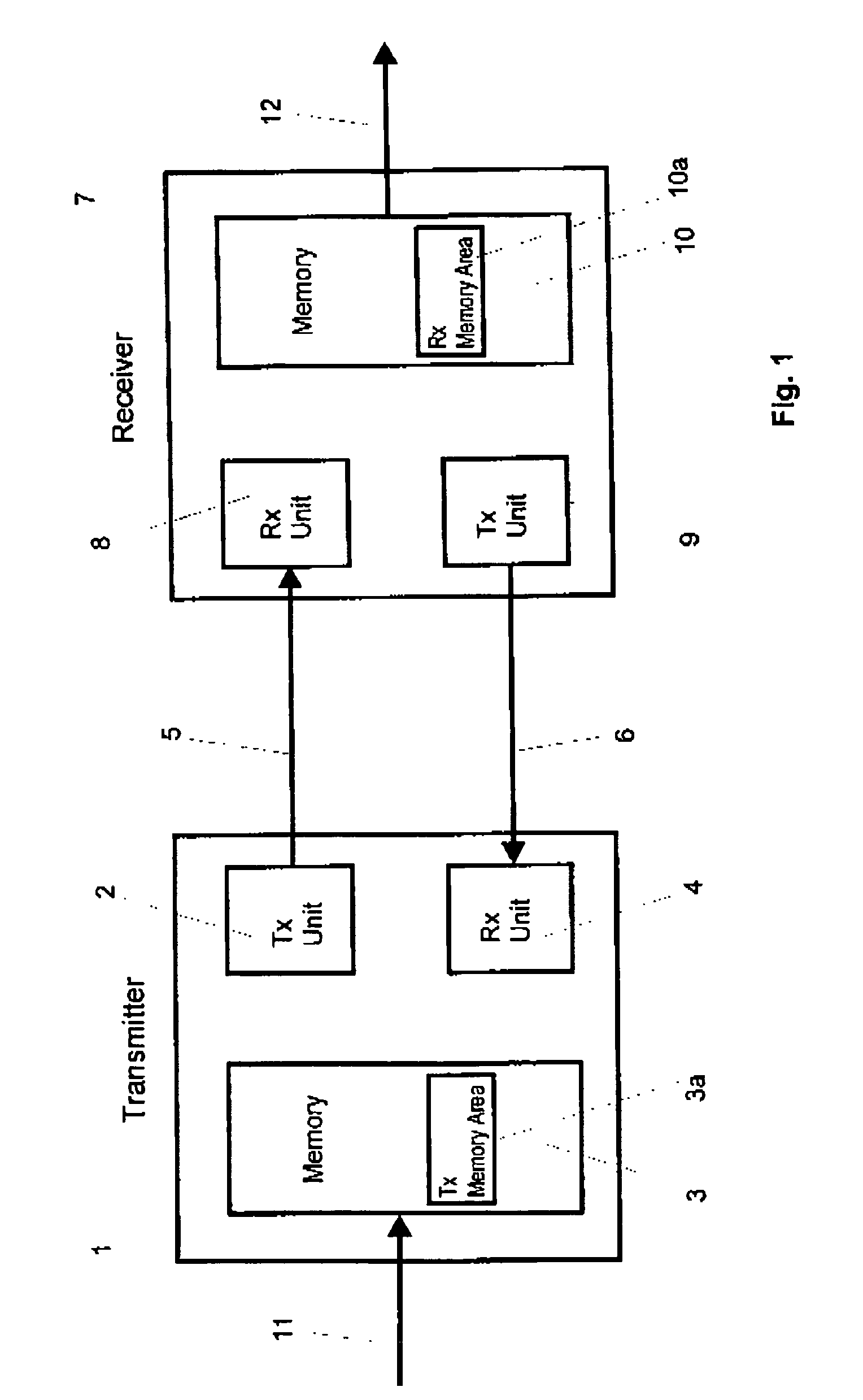
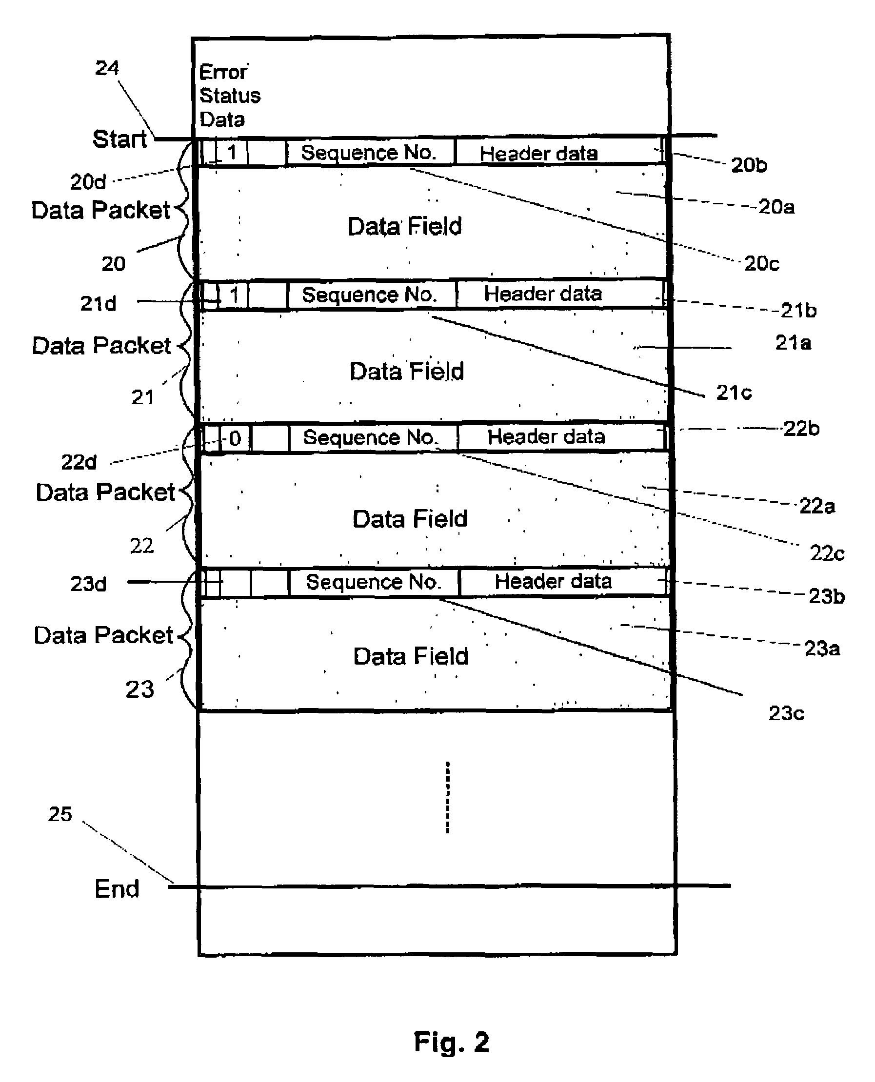
[0012]The invention proposes a method for synchronizing a transmitter memory area in a transmitter memory in a transmitter apparatus with a receiver memory area in a receiver memory in a receiver apparatus, where the transmitter memory area stores transmission data as transmission-data packets and the receiver memory area stores received data as received-data packets with associated error status data which respectively indicate an error status for the received-data packets, and where the method involves:[0013]t...


PUM


Abstract

The invention relates to a method for synchronizing a transmitter memory area in a transmitter memory in a transmitter apparatus with a receiver memory area in a receiver memory in a receiver apparatus, and to a receiver apparatus. The transmitter memory area stores transmission data as transmission-data packets and the receiver memory area stores received data as received-data packets with associated error status data which respectively indicate an error status for the received-data packets. Before a reference identification is generated in the receiver apparatus, which, following transmission using a feedback message in the transmitter apparatus, is used for memory area synchronization, the error status data for a plurality of the received-data packets are checked in the receiver apparatus until a first received-data packet is ascertained for which the error status data indicate no error status. An identification which identifies the first received-data packet is used to ascertain an identification for the current reference received-data packet taking into account a predetermined formation rule for forming the identifications for the received-data packets, from which identification the reference identification for the current reference received-data packet is derived.

Description

[0001]This application claims the benefit, under 35 U.S.C. §119 of German Patent Application 102004015159.8, filed Mar. 27, 2004.FIELD OF THE INVENTION[0002]The invention relates to a method for synchronizing memory areas in a transmitter apparatus and a receiver apparatus, particularly a transmitter memory area in a transmitter memory in a transmitter apparatus and a receiver memory area in a receiver memory in a receiver apparatus, and to a receiver apparatus.BACKGROUND OF THE INVENTION[0003]Increasingly, a plurality of electronic appliances are being interconnected using a network, even in the field of home electronics, so that electronic data can be interchanged between the appliances. The electronic data interchange between the electronic appliances then takes place within the network not just via cable connections between the appliances, for example on the basis of IEEE1394 bus systems, but also using wireless connections. There are already various systems which can be used fo...

Claims


Application Information

Patent Timeline
Patent Type & Authority Patents(United States)
IPC IPC(8): H04B1/38H04L1/00H04L1/16H04L1/18H04L12/56
CPCH04L1/1614H04L1/1642H04L1/1829H04L1/1874H04L47/26H04L1/1809H04L47/10H04L47/267H04L7/00H04L1/16
Inventor BRUNE, THOMAS
Owner MAGNOLIA LICENSING LLC
Why Eureka
Try Eureka