
Method for enabling power-saving mode

a power-saving mode and power-saving technology, applied in the field of methods for enabling power-saving modes, can solve the problems of increasing prolonging the standby period of batteries, and increasing power consumption of notebook computers, so as to reduce the power consumption of electronic devices

Active Publication Date: 2008-12-16
VIA TECH INC
View PDF7 Cites 4 Cited by
  • Summary
  • Abstract
  • Description
  • Claims
  • Application Information

AI Technical Summary

Benefits of technology

The present invention provides a method for reducing power consumption in electronic apparatuses by allowing them to enter a power-saving mode at proper timing. The method involves comparing a first input value with a first reference value, determining transmission indices based on the comparing result, and having the peripheral interface device enter the power-saving mode when the transmission indices indicate an inactive transmission state. The method can also be used when the port situation indices indicate an active transmission state. The invention also provides a method for enabling a power-saving mode for an electronic apparatus by allowing it to enter a power-saving mode when the peripheral interface device is not under a data-transceiving state. The technical effects of the invention include reducing power consumption and improving standby period for portable electronic devices.

Problems solved by technology

With the increasing number of peripheral devices connected thereto, the power consumption of an electronic apparatus increases.
Therefore, it is an important issue to prolong the standby period of the battery.
It is apparent that the power consumption of the notebook computer increases with the expansion functions applied thereto.

Method used


Image

  • Method for enabling power-saving mode
  • Method for enabling power-saving mode
  • Method for enabling power-saving mode

Examples


Embodiment Construction

[0026]The present invention will now be described more specifically with reference to the following embodiments. It is to be noted that the following descriptions of preferred embodiments of this invention are presented herein for purpose of illustration and description only; it is not intended to be exhaustive or to be limited to the precise form disclosed.

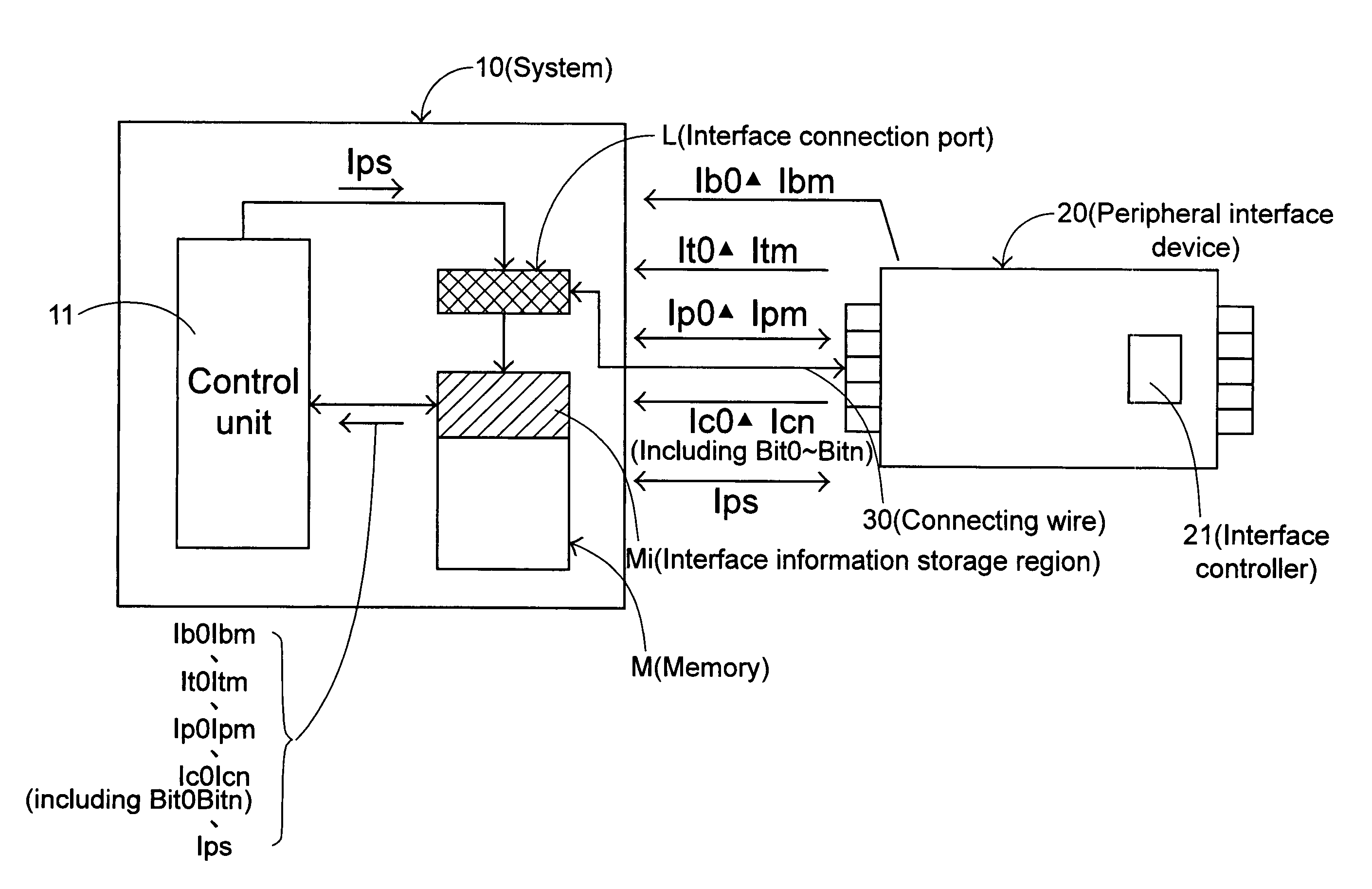
[0027]Please refer to FIG. 1. A system 10 includes an interface connection port L electrically connected to a peripheral interface device 20 via a connecting wire 30. The peripheral interface device 20 includes an interface controller 21 and a plurality of expansion ports (not shown) for connecting to a plurality of the peripheral devices (not shown).

[0028]For easily understanding the present invention, an exemplified embodiment is given herein. In this embodiment, the peripheral interface device 20 is an IEEE 1394 peripheral interface card and provides a plurality of transmission modes including an asynchronous request transmit ...


PUM


Abstract

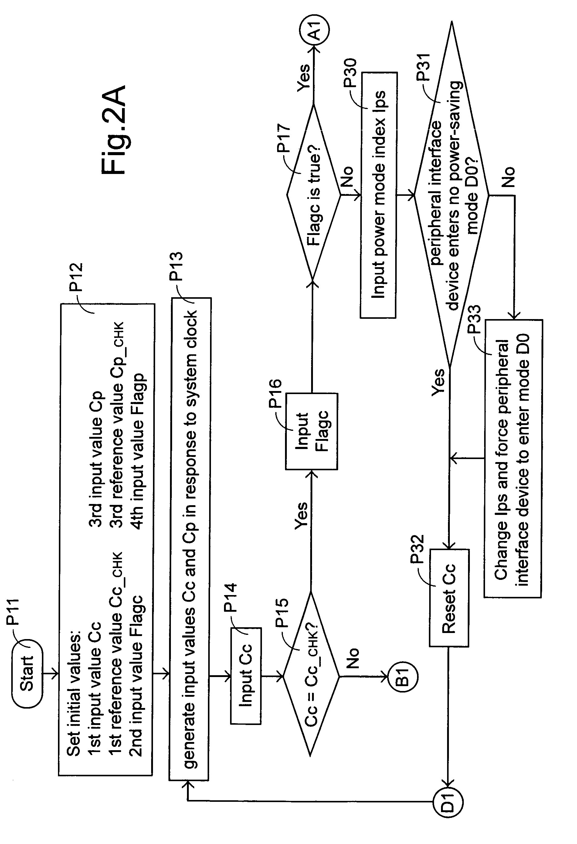
In a method for enabling a power-saving mode for an electronic apparatus, a power mode index Ips is determined according to transmission indices Bit0˜Bitn and / or port situation indices Ip0˜Ipm. For example, when the transmission indices Bit0˜Bitn are all under inactive states or when all the port situation indices Ip0˜Ipm are under disable states, the power mode index Ips indicates a highly power-saving mode D3. When less transmission indices are under inactive states or when less port situation indices Ip0˜Ipm are under port disable states, the power mode index Ips indicates a primary or intermediate power-saving mode D1 or D2. The power mode index Ips can also indicate no power-saving mode D0 when all transmission indices and / or port situation indices are active / enabled or the electronic apparatus is forced to remain normal power.

Description

CROSS REFERENCE TO RELATED PATENT APPLICATION[0001]This application is a continuation-in-part (CIP) application of application Ser. No. 10 / 290,131, filed Nov. 7, 2002, now abandoned the contents of which are incorporated herein by reference.FIELD OF THE INVENTION[0002]The present invention relates to a method for enabling a power-saving mode, and more particularly to a method for enabling a power-saving mode of a peripheral interface device.[0003]With the increasing number of peripheral devices connected thereto, the power consumption of an electronic apparatus increases. Especially for a portable electronic apparatus, e.g. a portable computer or a cellular phone, a battery which has limited power capacity is generally used as the power source. Therefore, it is an important issue to prolong the standby period of the battery.[0004]For example, a notebook computer is expandable by connecting thereto various peripheral devices via a peripheral interface device, such as IEEE 1394 interf...

Claims


Application Information

Patent Timeline
Patent Type & Authority Patents(United States)
IPC IPC(8): G06F1/32
CPCG06F1/3215
Inventor CHANG, YU-WEI
Owner VIA TECH INC
Learn More