Method for stabilizing a motor vehicle whose speed is reduced to a rest position and brake system for carrying out said method

a technology of brake system and motor vehicle, which is applied in the direction of brake cylinder, brake system, transportation and packaging, etc., can solve the problems of unusable vehicle movement, and achieve the effect of reliable transition

Active Publication Date: 2008-12-16
LUCAS AUTOMOTIVE GMBH
View PDF10 Cites 9 Cited by
  • Summary
  • Abstract
  • Description
  • Claims
  • Application Information

AI Technical Summary

Benefits of technology

[0004]In contrast to this, the object of the present invention is to provide a method for stabilising a motor vehicle which is decelerated into a rest position and a corresponding brake system for the motor vehicle which guarantee a more reliable transition from the service brake mode to the parking brake mode.
[0006]In other words, this means that, according to the present invention, the service brake simulates the parking brake mode before an actual transition to this parking brake mode. The driver therefore senses whether the braking forces which are available in the parking brake mode are sufficiently high to hold the vehicle in the desired position. If the vehicle remains in the desired position, the driver will make no changes to the braking state, which means that he will park the vehicle in the manner to which he is accustomed. As the driver makes no changes to the braking state, a transition from the service brake mode via the mode simulating the braking-force distribution of the parking brake to the parking brake mode takes place. On the other hand, if the basic conditions are such that, during the mode simulating the braking-force distribution of the parking brake, an undesirable movement of the vehicle occurs, for example because the roadway does not offer sufficient grip in the region of the wheels braked during the parking brake mode or because the loading or trailer load of the vehicle is too great to hold the vehicle immobile solely with the wheels braked in the parking brake mode, the driver senses this immediately during the mode simulating the braking-force distribution of the parking brake and can react accordingly. A reaction of this kind results, for example, in the brake pedal being depressed again and therefore a corresponding increase in the braking force in the context of the service brake mode, also called “switching-back” in the following, so that re-activation of the parking brake can be initiated while passing through the transition phase, although at a higher braking force level. The invention can therefore prevent undesirable movements of the vehicle which surprise the driver following a transition to the parking brake mode.
[0010]As regards the change in the braking force at individual vehicle wheels, according to one development of the invention relating to the automatic braking-force distribution, the braking force of the service brake is steadily reduced at a front vehicle axle and built up at selected wheels, in particular at wheels of a rear vehicle axle, until the braking-force distribution of the parking brake is attained. It is also possible in this connection for the entire braking force of the service brake to be transferred to the holding force of the parking brake following the second instant of the time interval. It is thereby possible to guarantee a sufficiently high holding force in the parking brake mode to guarantee a reliable parking brake mode.
[0013]According to one development of the invention, the stability control of the parking brake and / or of the service brake is integrated into a stability system of the vehicle. An integral solution of this kind enables the invention to be implemented in a relatively simple manner by using the control of the stability system.

Problems solved by technology

On the other hand, if the basic conditions are such that, during the mode simulating the braking-force distribution of the parking brake, an undesirable movement of the vehicle occurs, for example because the roadway does not offer sufficient grip in the region of the wheels braked during the parking brake mode or because the loading or trailer load of the vehicle is too great to hold the vehicle immobile solely with the wheels braked in the parking brake mode, the driver senses this immediately during the mode simulating the braking-force distribution of the parking brake and can react accordingly.
In other words, this means that, when the driver notices an undesirable movement of the vehicle in the mode simulating the braking-force distribution of the parking brake, he also does not actuate the service brake again—by depressing the brake pedal—and therefore parks the vehicle in the usual way.

Method used


Image

  • Method for stabilizing a motor vehicle whose speed is reduced to a rest position and brake system for carrying out said method
  • Method for stabilizing a motor vehicle whose speed is reduced to a rest position and brake system for carrying out said method
  • Method for stabilizing a motor vehicle whose speed is reduced to a rest position and brake system for carrying out said method

Examples


Embodiment Construction

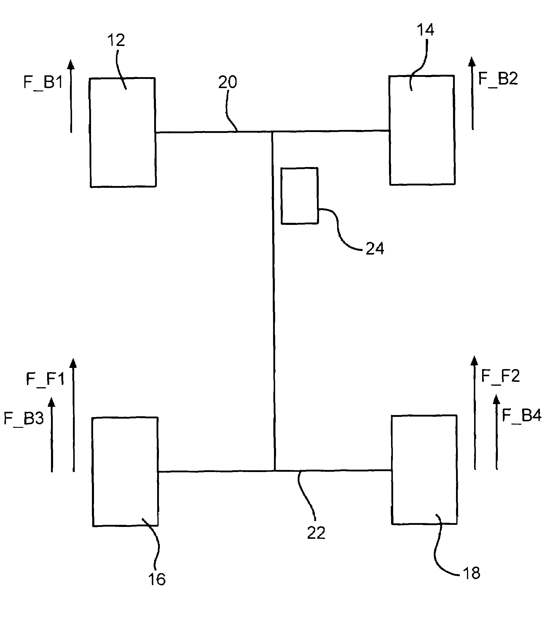
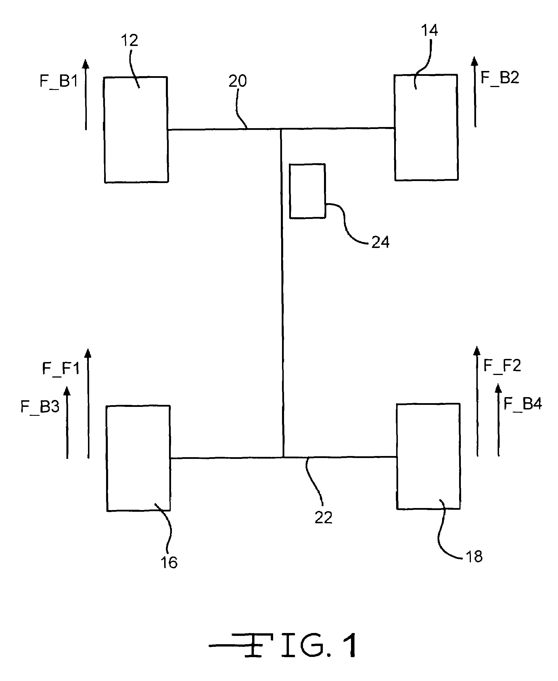
[0018]FIG. 1 shows a schematically represented motor vehicle which is generally designated by 10. This comprises four wheels, namely the two front wheels 12 and 14 and the two rear wheels 16 and 18.

[0019]The two front wheels 12 and 14 are coupled via a front axle 20, while the two rear wheels are coupled via a rear axle 22. A service brake, the control of which is generally designated by 24, acts on all four wheels 12, 14, 16 and 18. In the service brake mode the service braking force F_B1 acts on the front wheel 12, the service braking force F_B2 on the front wheel 14, the service braking force F_B3 on the rear wheel 16 and the service braking force F_B4 on the rear wheel 18. However in the parking brake mode, for example when the vehicle has been parked, in the example holding forces only act on the two rear wheels 16 and 18, namely the holding force F_F1 on the rear wheel 16 and the holding force F_F2 on the rear wheel 18. These holding forces are applied by the parking brake.

[00...


PUM


Abstract

In a method for stabilising a motor vehicle which is decelerated into a rest position and in a corresponding motor vehicle brake system which is provided with a service brake and a parking brake which can be actuated independently of the driver, when activation of the parking brake is initiated, the service brake changes from a first braking-force distribution of a service brake mode to a mode simulating a second braking-force distribution of the parking brake, and a switch-back to the first braking-force distribution of the service brake mode is enabled at least during the transition.

Description

CROSS-REFERENCE TO RELATED APPLICATIONS[0001]This application is a continuation of International Application No. PCT / EP2004 / 012153 filed Oct. 27, 2004, the disclosures of which are incorporated herein by reference, and which claimed priority to German Patent Application No. 103 51 025.7 filed Oct. 31, 2003, the disclosures of which are incorporated herein by reference.BACKGROUND OF THE INVENTION[0002]The present invention relates to a method for stabilising a motor vehicle which is decelerated into a rest position and is provided with a service brake and a parking brake which can be actuated independently of the driver, and to a corresponding motor vehicle brake system.[0003]It is already known to provide motor vehicle brake systems with a service brake and a parking brake which can be actuated independently of the driver. For example, EP 0 825 081 B1, and corresponding U.S. Pat. No. 6,019,436 A1, both of which are incorporated by reference herein, describes a brake system of this k...

Claims


Application Information

Patent Timeline
Patent Type & Authority Patents(United States)
IPC IPC(8): B60T13/00B60T13/74
CPCB60T13/74
Inventor SAEWE, DIRKWAGNER, CHRISTOPH
Owner LUCAS AUTOMOTIVE GMBH
Why Eureka
Try Eureka