
Apparatus for transmitting sound in a motor vehicle

a technology for motor vehicles and apparatuses, applied in the direction of machines/engines, combustion air/fuel air treatment, instruments, etc., can solve the problem that the potential arrangement described there is not fully utilized in regard to the efficiency that can be achieved in sound transmission, and achieve the effect of preventing leakage in the bearing area, increasing positional accuracy, and certain rigidity and/or load-bearing capacity

Inactive Publication Date: 2008-12-16
MANN HUMMEL GMBH
View PDF15 Cites 13 Cited by
  • Summary
  • Abstract
  • Description
  • Claims
  • Application Information

AI Technical Summary

Benefits of technology

[0006]Another object is to provide a device for transmitting sound in a motor vehicle in which sound transmission is achieved with an increased efficiency.
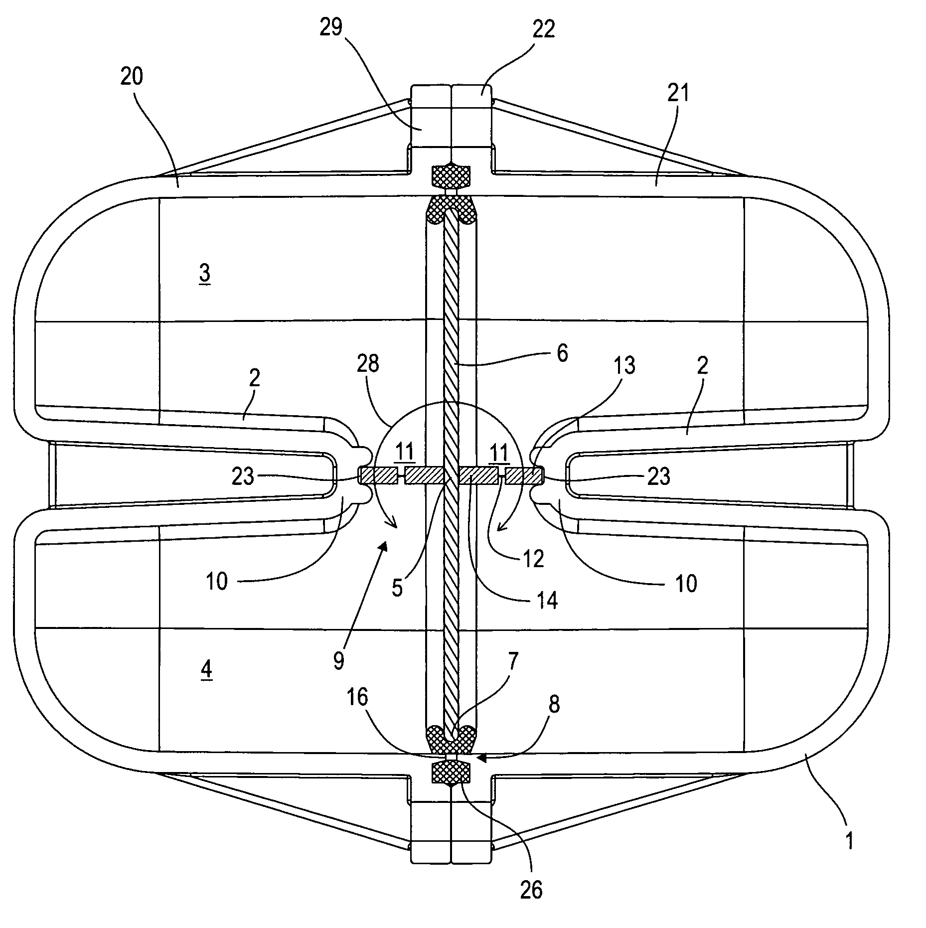
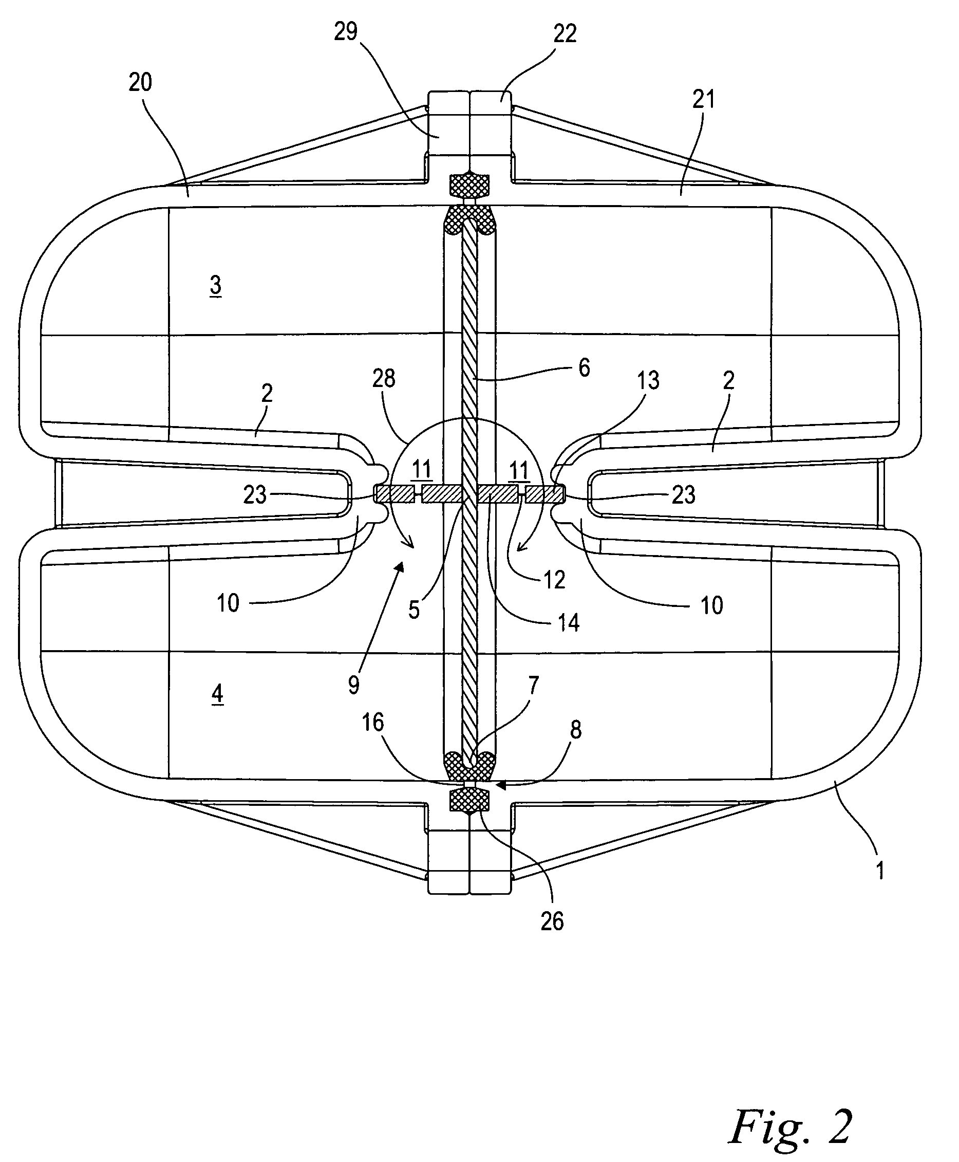
[0013]In an advantageous embodiment, the outer frame is held in a form-fitting manner in a groove at the edge of the pivot bearing opening. This yields the possibility of simplified assembly in that the outer frame is clamped in the corresponding groove sections when the housing parts are joined together. The fact that the outer frame is clamped together in a form-fitting manner creates a good sealing effect within the arrangement and also with respect to the outside, in addition to ensuring precise fixation of the transmission valve in an accurate position. The resulting clamping forces are absorbed by the outer frame and are kept away from the membrane and / or the transmission valve so that their free mobility is ensured.

Problems solved by technology

The potential of the arrangement described there is not fully utilized with regard to the efficiency that can be achieved in sound transmission.

Method used


Image

  • Apparatus for transmitting sound in a motor vehicle
  • Apparatus for transmitting sound in a motor vehicle
  • Apparatus for transmitting sound in a motor vehicle

Examples


Embodiment Construction

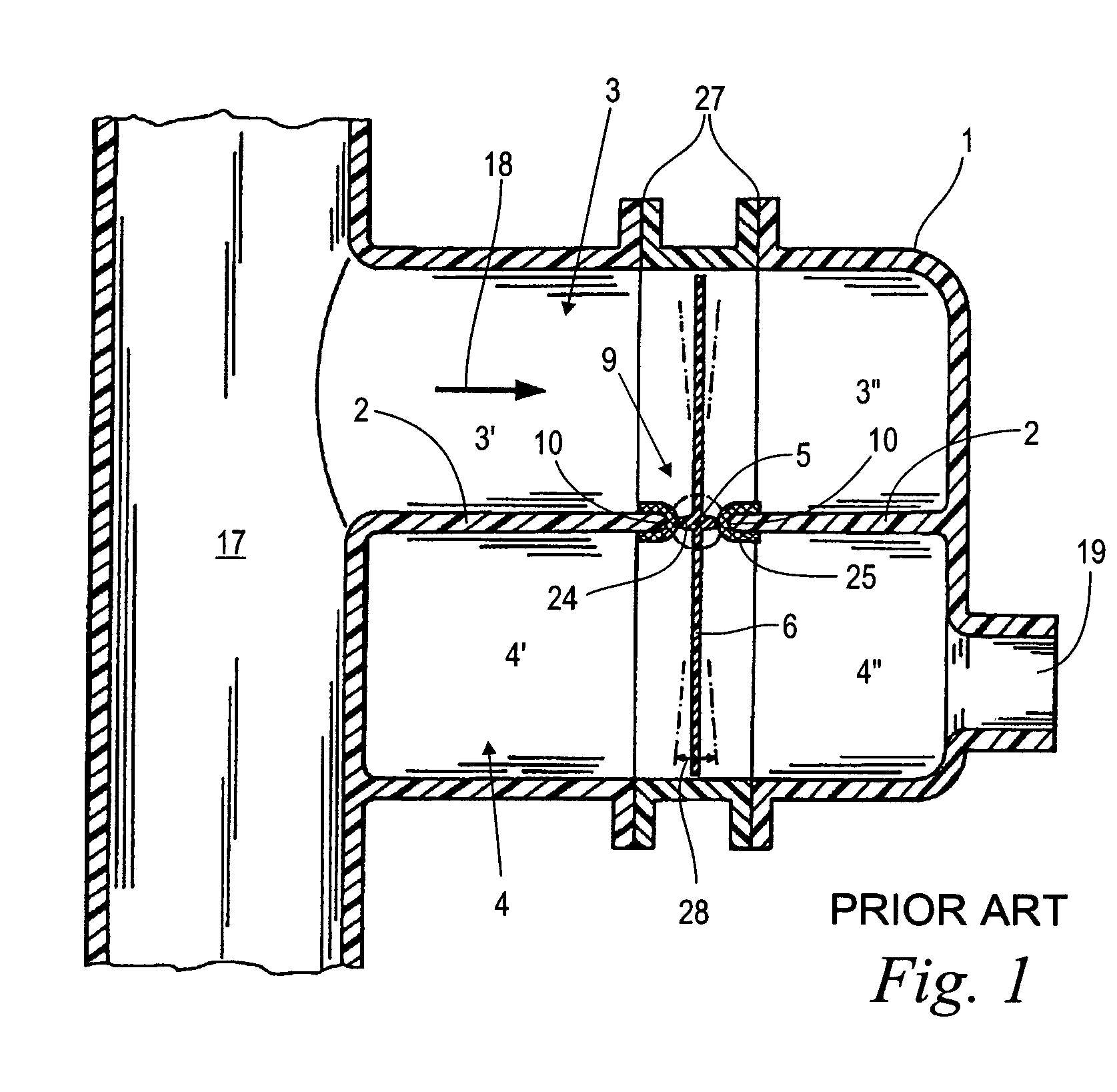
[0019]FIG. 1 shows a sectional diagram of a prior art device for sound transmission in a motor vehicle. The device includes a housing 1 having an inside partition 2, where the housing 1 and the inside partition 2 define or delimit two separate subspaces 3 and 4. A part of the housing 1 is integrally molded on an intake manifold 17 of an internal combustion engine (not shown) of a motor vehicle, with the first subspace 3 being connected to the interior of the intake manifold 17 in a manner that transmits sound pressure. The partition 2 creates a fluid separation of the first subspace 3 from the second subspace 4.

[0020]A transmission valve 6 is provided, disposed in a pivot bearing opening 9 through the partition 2 and mounted to pivot about a pivot axis 5 in the partition 2 and / or in the pivot bearing opening 9. The transmission valve 6 extends on both sides from the pivot axis 5 up to close to the inside wall of the housing 1, forming a small gap and thereby dividing the two subspac...


PUM


Abstract

An apparatus for transmitting sound in a motor vehicle having a housing (1) with an inner partition (2), which together define two separate subspaces (3, 4). A transmission valve (6) which separates the two subspaces (3, 4) is provided in a pivot bearing opening (9) in the partition (2) and is mounted to pivot about a pivot axis (5) in the area of the pivot bearing opening (9). The first subspace (3) is connected in a manner capable of transmitting sound to an intake manifold (17) of an internal combustion engine, and the second subspace (4) is connected in a manner capable of transmitting sound to an interior space of the motor vehicle. The gap (11) between an edge (10) of the pivot bearing opening (9) and the transmission valve (6) is sealed in a pressure-tight manner by a membrane (12).

Description

BACKGROUND OF THE INVENTION[0001]The present invention relates to a device for sound transmission in a motor vehicle.[0002]The propulsion motors of modern motor vehicles are very smooth-running internal combustion engines which generate operating noise that is hardly audible in the interior of the vehicle. Under some circumstances, the operating noise of the internal combustion engine is audible through the secondary noise of the turning wheels, a ventilation system that is turned on, etc. Under certain circumstances, it may be desirable to audibly transmit the operating noise of the driving engine into the interior of the vehicle.[0003]Published European patent application no. EP 1,306,829 describes a device for transmitting the noise of an internal combustion engine in which a housing having a partition delimits or defines two separate subspaces. The partition is interrupted by a pivotable valve which separates the two subspaces. The first subspace is connected to the intake manif...

Claims


Application Information

Patent Timeline
Patent Type & Authority Patents(United States)
IPC IPC(8): F01N1/02F01N1/20G08B3/02F01N1/16F02M35/104
CPCG10K11/22F02M35/1272F02M35/1294
Inventor ALEX, MATTHIASPFEIFFER, FRANK
Owner MANN HUMMEL GMBH
Learn More