
Integrated fluidized bed ash cooler

a fluidized bed and ash cooler technology, applied in the field of fluidized bed ash coolers, can solve the problems of complex solids transfer from the furnace to the ash cooler, and the bottom ash removed from the fluidized bed combustors contains a significant amount of heat, so as to reduce the size, weight and cost of the ash cooler

Active Publication Date: 2008-12-16
THE BABCOCK & WILCOX CO
View PDF13 Cites 17 Cited by
  • Summary
  • Abstract
  • Description
  • Claims
  • Application Information

AI Technical Summary

Benefits of technology

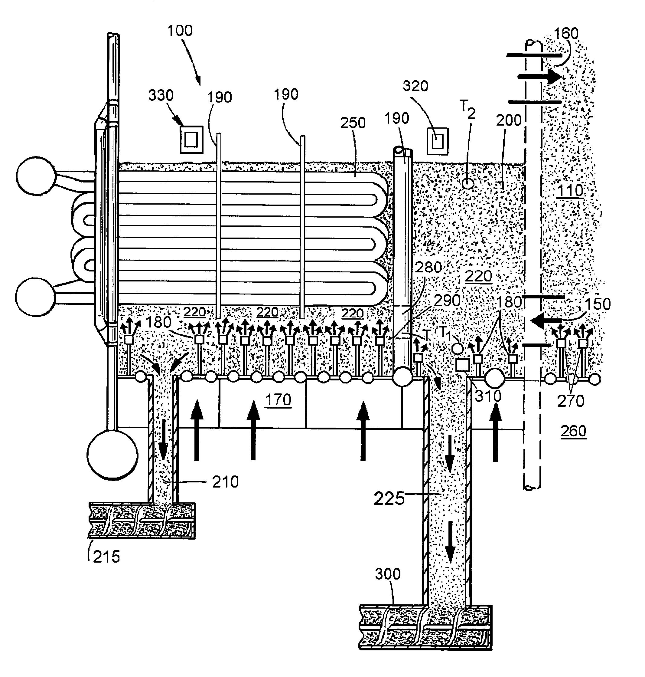
The present invention provides a fluidized bed ash cooler for cooling bottom ash solids from a fluidized bed furnace. The ash cooler comprises at least two fluidized bed sections positioned in series along a solids flow path, each section containing fluidizing means. The first section along the solids path is separated from a following section with a threshold, the first section containing means for measuring the bed temperature in the vicinity of the fluidizing means and at a higher elevation within the fluidized bed. Means are also provided for removing oversize bed material from the first section. The invention allows for reductions in the size, weight, and cost of the ash cooler. The invention is simple in design, rugged in construction, and economical to manufacture.

Problems solved by technology

The bottom ash removed from fluidized bed combustors contains a significant amount of heat.
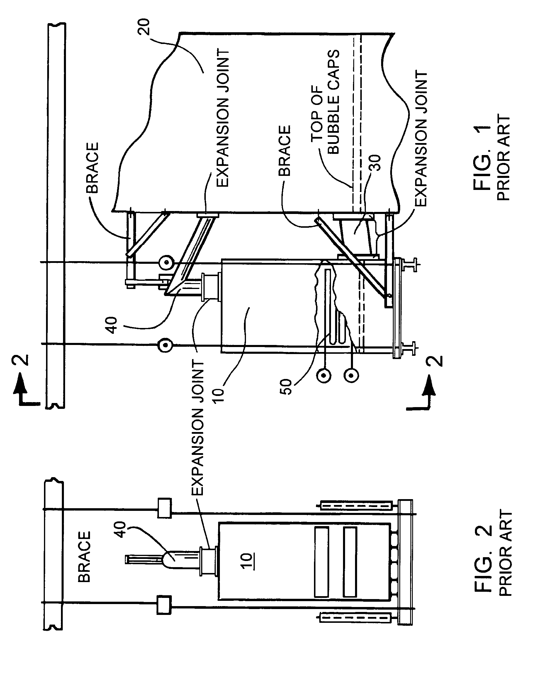
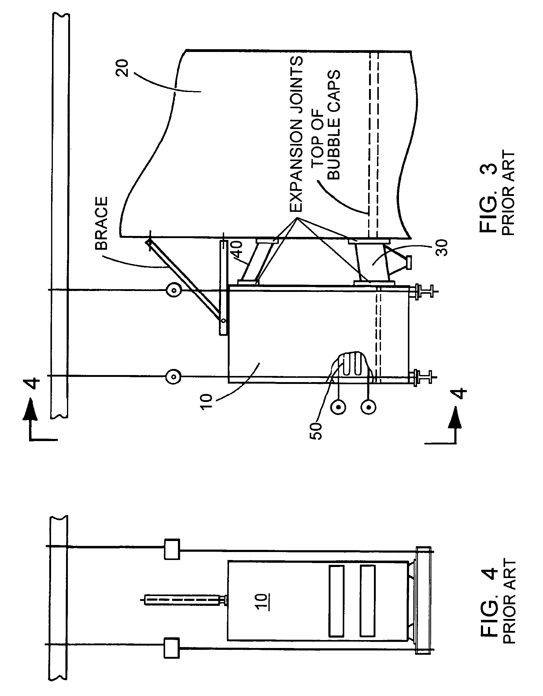
While the existing ash coolers provide necessary ash cooling and enhance boiler efficiency by returning the heat absorbed from the ash back to the boiler system, the existing ash coolers have several shortcomings including: a complicated support structure, the need for high-temperature expansion joints to accommodate differences in thermal expansion between the ash cooler and the furnace, and complexity of solids transfer from the furnace to the ash cooler.

Method used


Image

  • Integrated fluidized bed ash cooler
  • Integrated fluidized bed ash cooler
  • Integrated fluidized bed ash cooler

Examples


Embodiment Construction

[0021]Referring to the drawings generally wherein like reference numerals designate the same or functionally similar elements throughout the several drawings, and to FIGS. 5-9 in particular, there is illustrated a first embodiment of the integrated fluidized bed ash cooler according to the present invention, generally designated 100.

[0022]As illustrated in FIGS. 5 and 6, the integrated fluidized bed ash cooler 100 is provided as an integral part of a circulating fluidized bed (CFB) furnace 110 having furnace walls 120. As shown in FIG. 6, the ash cooler 100 is preferably formed of membrane tube wall panels 130 one of which is a part of one of the furnace walls 120. While it is most likely that such membrane wall construction would be employed for both the fluidized bed furnace 110 and the fluidized bed ash cooler 100, it is possible that an uncooled enclosure wall construction could be employed for both the ash cooler 100 and the fluidized bed furnace 110. The principles of the pres...


PUM


Abstract

An integrated fluidized bed ash cooler for a fluidized bed boiler, particularly a circulating fluidized bed (CFB) boiler, employs at least two fluidized bed sections positioned in series along a solids flow path. Each section contains fluidizing means, the first section along the solids path being separated from a following section with a threshold. The first section contains means for measuring a bed temperature in the vicinity of the fluidizing means and at a higher elevation within the fluidized bed. Means are provided for removing oversized bed material from the first section to facilitate the removal of ash while minimizing the possibility of ash plugging during operation.

Description

FIELD OF THE INVENTION[0001]The present invention relates, in general, to fluidized bed ash coolers and, more particularly, to an integrated fluidized bed ash cooler which facilitates the removal of ash while minimizing the possibility of ash plugging during operation.BACKGROUND OF THE INVENTION[0002]Fluidized bed bottom ash coolers are widely used in fluidized bed combustion technology. The bottom ash removed from fluidized bed combustors contains a significant amount of heat. Removal of the heat in the bottom ash reduces the temperature of the ash, thereby facilitating handling and disposal of same. Recovery of the heat in the bottom ash is also desirable in order to enhance the overall thermal efficiency of the fluidized bed combustion plant. Fluidization of the ash in the ash cooler sharply enhances heat transfer between the ash and the cooling medium which allows for the size of the ash cooler to be reduced.[0003]Typical existing prior art fluidized bed bottom ash coolers for a...

Claims


Application Information

Patent Timeline
Patent Type & Authority Patents(United States)
IPC IPC(8): F23C10/24
CPCF23C10/18F23J1/00F23J2900/01002
Inventor MARYAMCHIK, MIKHAILSZMANIA, MICHAEL J.JAMES, DAVID E.WALKER, DAVID J.WIETZKE, DONALD L.
Owner THE BABCOCK & WILCOX CO
Learn More