
Multi-chain signal detection and gain control for automatic gain control systems

a gain control and multi-chain technology, applied in gain control, diversity/multi-antenna system, polarisation/directional diversity, etc., can solve the problems of bit errors in the signal, overloading and possibly damaging certain components, and portions of the signal taking the longer path can undetectable lose energy

Active Publication Date: 2008-12-09
QUALCOMM INC
View PDF17 Cites 54 Cited by
  • Summary
  • Abstract
  • Description
  • Claims
  • Application Information

AI Technical Summary

Benefits of technology

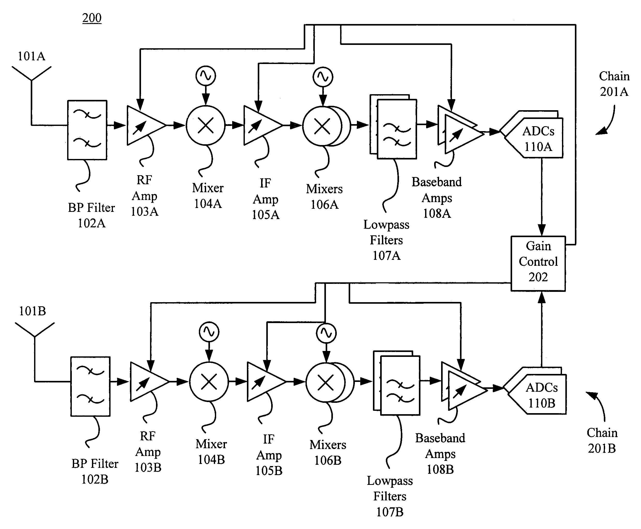
[0011]A wireless local area network (WLAN) system can have multiple antennas to improve signal detection and decoding. A WLAN receiver in such a system includes multiple amplifiers that can appropriately size an incoming signal. The amplifiers of a chain of the WLAN receiver, i.e. an antenna and associated receiver components, can be adjusted with computed gains.
[0015]In one embodiment, each AGC pre-processor can include a first filter that eliminates a DC component of the processed signal and a power detect unit. This power detect unit receives the output of the first filter and provides a first power value to the AGC controller. Each AGC pre-processor can further include a set of filters, a second power detect unit, and a correlator. The set of filters can reduce a required data-sampling rate, remove adjacent blockers, and eliminate a DC component of the processed signal. The second power detect unit receives an output of the set of filters and provides a second power value to the AGC controller. The first and second power values can determine whether a quick drop gain technique or a base gain control technique is performed on each chain as well as determine whether a received signal is within an acceptable range on at least one chain.

Problems solved by technology

Specifically, an amplified strong signal can distort incoming signals, thereby overloading and possibly damaging certain components (e.g. front-end components, such as the ADCs).
Portions of the signal taking the longer path can undesirably lose energy.
Moreover, combining the received portions of the signal can result in some distortion, perhaps even causing bit errors in the signal.
These “one size fits all” techniques fail to optimize amplifier performance.

Method used


Image

  • Multi-chain signal detection and gain control for automatic gain control systems
  • Multi-chain signal detection and gain control for automatic gain control systems
  • Multi-chain signal detection and gain control for automatic gain control systems

Examples


Embodiment Construction

[0094]Although illustrative embodiments have been described in detail herein with reference to the accompanying figures, it is to be understood that the invention is not limited to those precise embodiments. They are not intended to be exhaustive or to limit the invention to the precise forms disclosed. As such, many modifications and variations will be apparent to practitioners skilled in this art.

[0095]For example, an adjacent blocker is defined as an interference signal adjacent to or overlapping the frequency band of interest, whereas an alternate blocker is defined as an interference signal farther away from the frequency band of interest. With a worst case of 6 dB for an adjacent blocker and 32 dB for an alternate blocker, a received blocker at the ADC input can be 12 dB higher than the in-band signal. Therefore, in one embodiment, an analog channel filter and / or anti-aliasing filter may advantageously be placed before the ADCC to perform an adjacent block rejection of 4 dB an...


PUM


Abstract

A wireless local area network (WLAN) system can have multiple antennas to improve signal detection and decoding. A WLAN receiver in such a system includes multiple amplifiers that can appropriately size an incoming signal and an automatic gain control unit to process the received incoming signals. The amplifiers of a chain of the WLAN receiver, i.e. an antenna and associated receiver components, can be adjusted with computed gains. To optimize the wireless system detection and decoding, the automatic gain control unit can advantageously compute these gains for each amplifier in the WLAN receiver.

Description

BACKGROUND OF THE INVENTION[0001]1. Field of the Invention[0002]The present invention relates to an automatic gain control (AGC) system and in particular to an AGC system using multi-chain signal detection and gain control.[0003]2. Description of the Related Art[0004]WLAN Receiver With Single Antenna: Overview[0005]Receivers are ubiquitous circuits in wireless systems (e.g. such as wireless local area networks (WLANs)). FIG. 1 illustrates a simplified receiver 100 for receiving signals in a WLAN environment. In receiver 100, a bandpass filter 102 receives the incoming signals from an antenna 101 and outputs a predetermined band of frequencies (while excluding those frequencies higher and lower than the predetermined band). A variable gain RF amplifier 103 can provide an initial amplification to that predetermined band of frequencies. A mixer 104 converts those amplified signals (using a signal from a local oscillator) into intermediate frequency (IF) signals, which are then amplifie...

Claims


Application Information

Patent Timeline
IPC IPC(8): H04L27/08
CPCH03G3/3068H03G3/3078
Inventor TEHRANI, ARDAVAN MALEKIZHANG, XIAORUHUSTED, PAUL J.GILBERT, JEFFREY M.
Owner QUALCOMM INC
Learn More