
Monopolar DC to bipolar DC to AC converter

a monopolar dc and bipolar technology, applied in the field of electric power conversion topology and apparatus, can solve the problems of heavy and expensive transformers, negative impact on overall inverter conversion efficiency, and low conversion efficiency of inverter,

Active Publication Date: 2008-12-09
XANTREX TECH
View PDF10 Cites 194 Cited by
  • Summary
  • Abstract
  • Description
  • Claims
  • Application Information

AI Technical Summary

Benefits of technology

"The invention is an improvement over prior art inverters for converting power from photovoltaic cells to an AC load. The new invention has a simplified topology and reduces the complexity, cost, and conversion losses compared to the prior art. It achieves this by using a 1½ conversion step instead of 2 conversion steps for systems with grounded PV arrays, and effectively less than 1½ conversion steps for systems with ungrounded PV arrays. This results in at least 25% less complexity, cost, and conversion losses over the prior art."

Problems solved by technology

Power is lost in each of these power conversion stages with a negative impact on overall inverter conversion efficiency.
Second, transformer 60 operates at the electric utility line frequency and as such is heavy and expensive.
Power is lost in each of these power conversion stages with a negative impact on overall inverter conversion efficiency.
Also, additional conversion losses are had by charging and discharging the parasitic PV-array-to-earth-ground capacitance.
This approach, however, yields the lowest conversion efficiencies because there are too many semiconductor losses.
Designs based on these topologies are complex, have high component parts counts and, as such, are less robust.
In all prior art topologies discussed, 100% of the throughput power is processed twice and power is lost in each conversion stage.

Method used


Image

  • Monopolar DC to bipolar DC to AC converter
  • Monopolar DC to bipolar DC to AC converter
  • Monopolar DC to bipolar DC to AC converter

Examples


Embodiment Construction

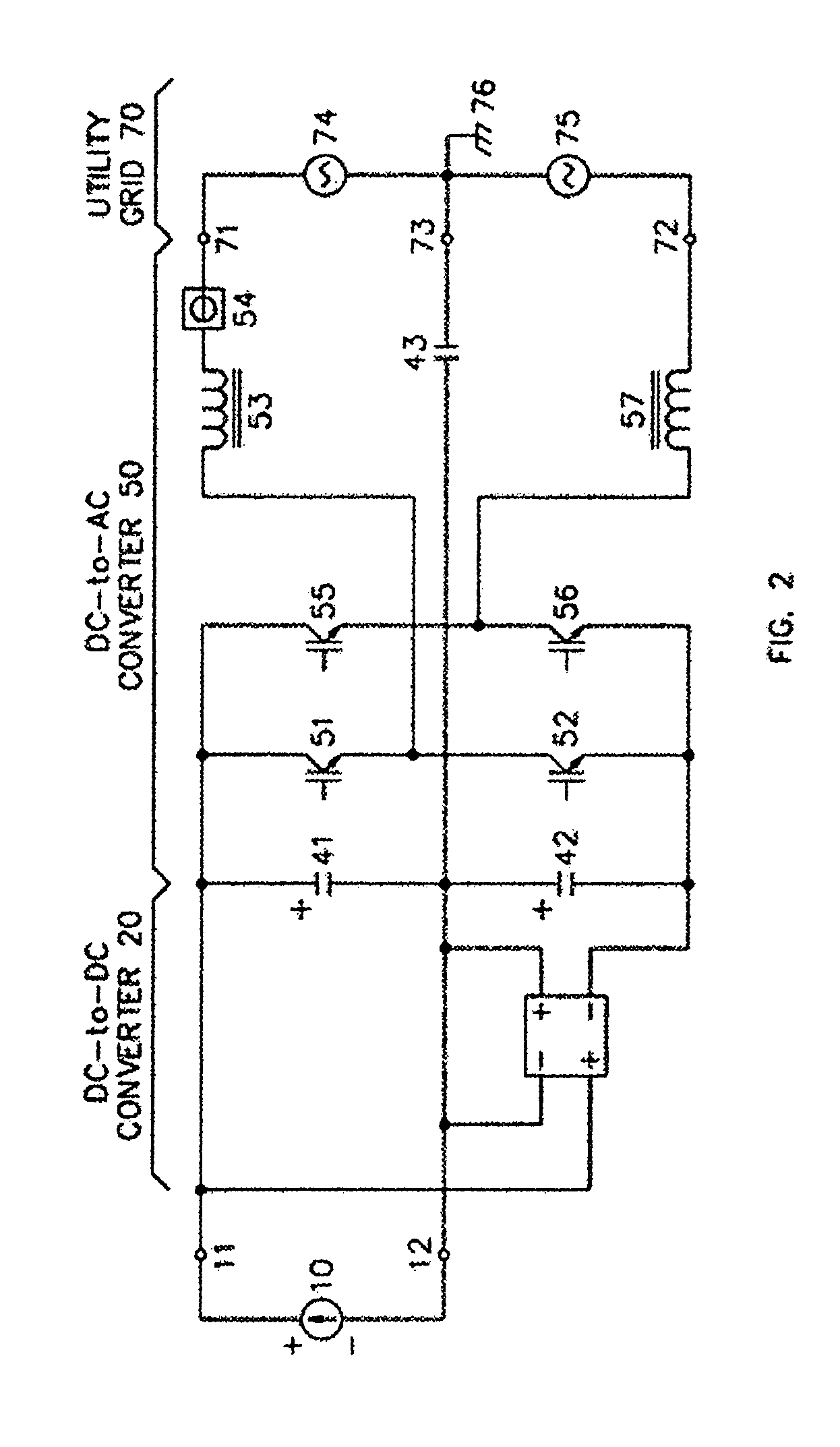
[0017]A number of slightly different DC-to-AC inverter topologies will be disclosed, all with the common characteristic that less than 1½ conversion stages are used or, stated differently, that at least ½ of the power from a DC source is converted only once in the DC-to-AC conversion process. The topologies are variations of the central idea of the invention configured to facilitate different options for the PV array grounding and the utility grid configuration.

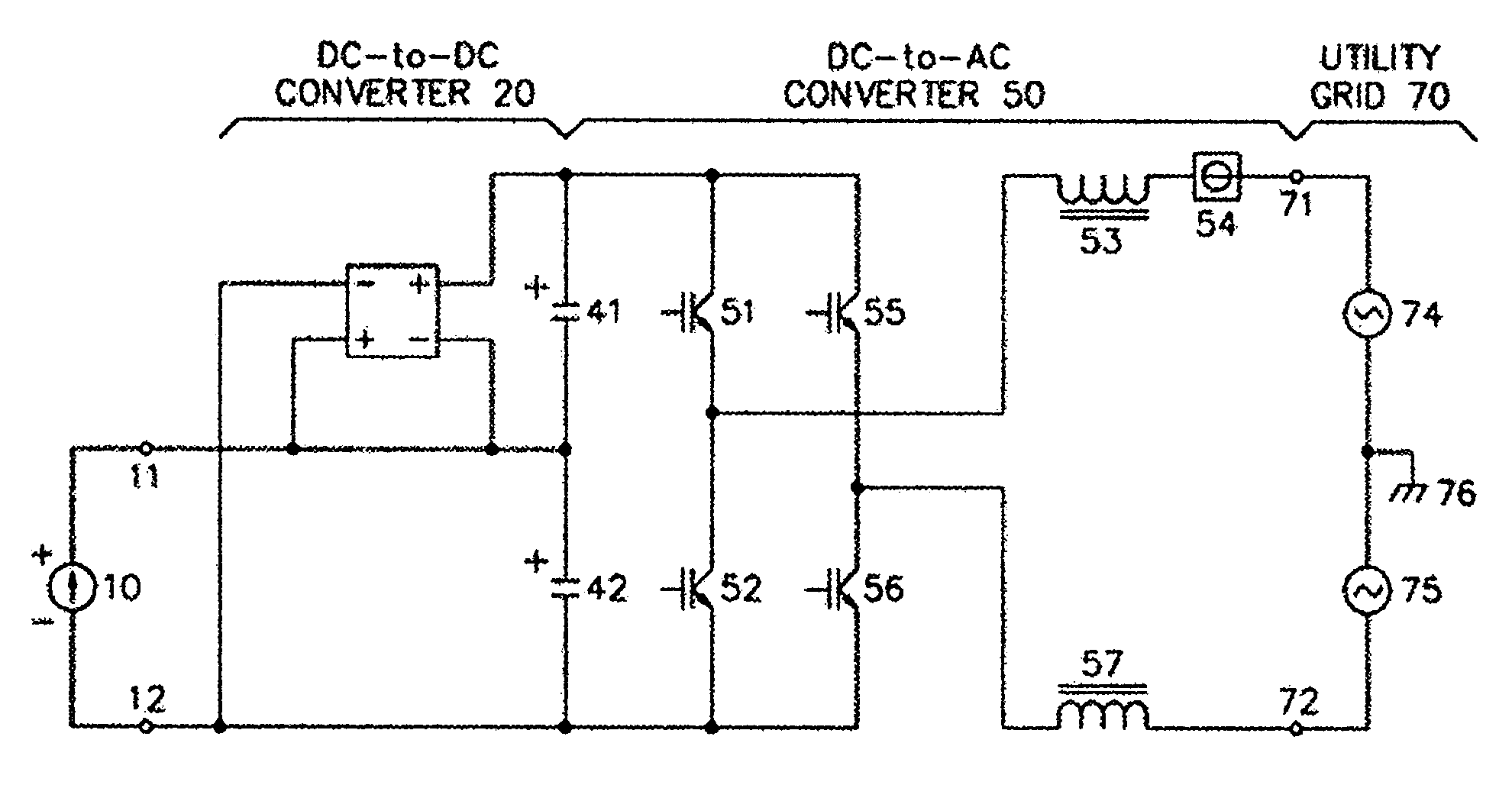
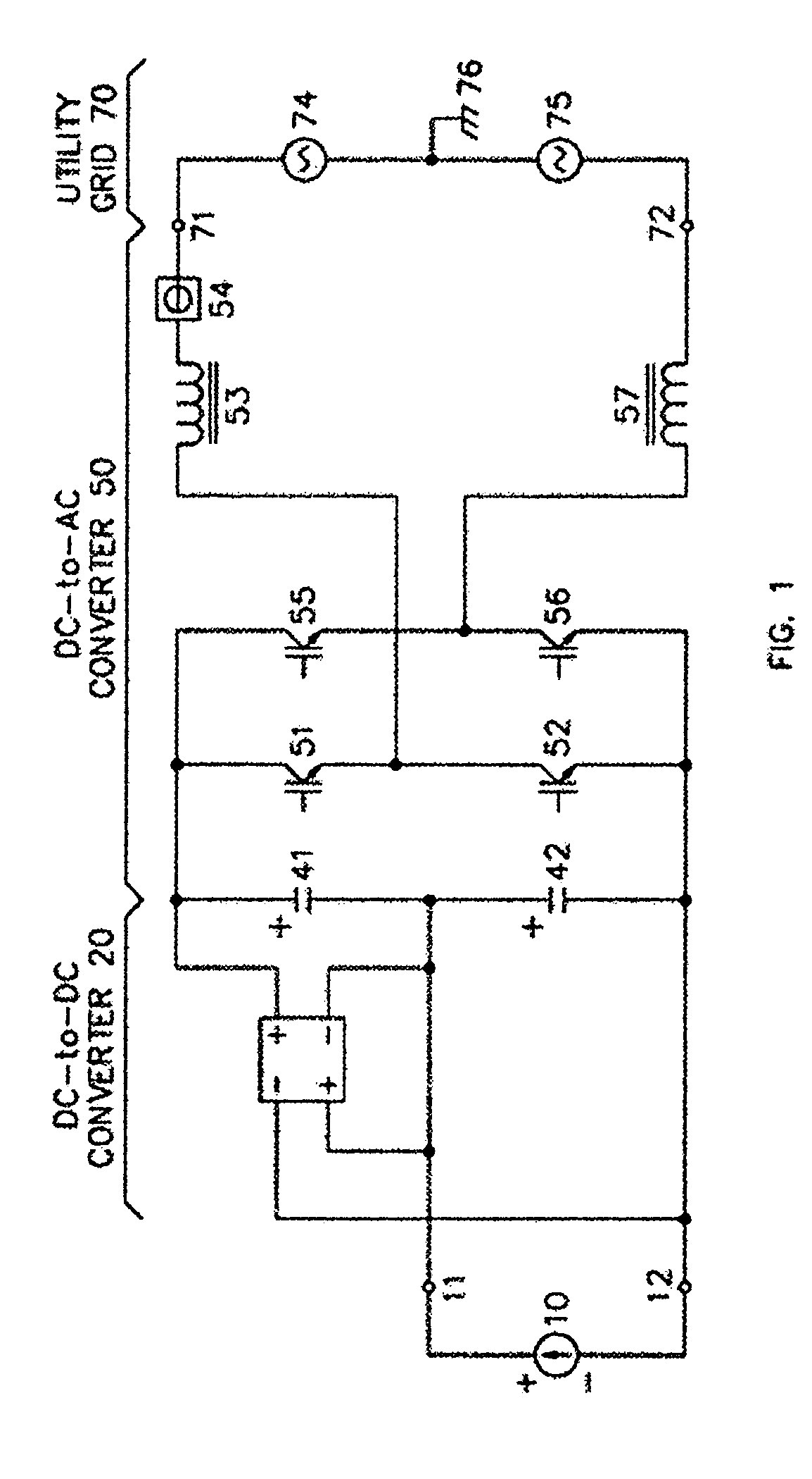
[0018]The preferred embodiment of the invention is shown in FIG. 1. PV array 10 is connected to inverter input terminals 11 and 12, across energy storage capacitor 42 and across the input of DC-to-DC converter 20. The output of DC-to-DC converter 20 is connected to energy storage capacitor 41. Capacitors 41 and 42 comprise the “bipolar energy storage element” referred to in the claims. Transistors 51, 52, 55 and 56 are connected in a typical full-bridge arrangement. For clarity, anti-parallel diodes across each transistor are...


PUM


Abstract

An electrical DC-to-AC power conversion apparatus is disclosed that is primarily intended for use with solar photovoltaic sources in electric utility grid-interactive applications. The invention improves the conversion efficiency and lowers the cost of DC-to-AC inverters. The enabling technology is a novel inverter circuit topology, where throughput power, from DC source to AC utility, is processed a maximum of 1½ times instead of 2 times as in prior-art inverters. The AC inverter output configuration can be either single-phase, split-phase or poly-phase.

Description

CROSS-REFERENCE TO RELATED APPLICATIONS[0001]This application is a continuation-in-part of U.S. patent application Ser. No. 10 / 248,826, entitled “Monopolar DC to Biopolar to AC Converter,” filed on Feb. 21, 2003, which issued as U.S. Pat. No. 7,064,969 on Jun. 20, 2006.BACKGROUND OF INVENTION[0002]The invention is an electrical power conversion topology and apparatus for converting and delivering power from a mono-polar DC source to an AC load.[0003]Photovoltaic (PV) cells produce power over a wide voltage range depending on the amount of sunlight and the temperature of the photovoltaic cell. There are National Electric Code and class-of-equipment restrictions that make PV arrays much more cost effective when sized for a maximum of 600 Vdc. In order to source AC power into the electric utility grid, over the expected range of DC voltages, prior art utility-interactive inverters use two power conversion stages.[0004]FIG. 6 shows one common prior art inverter topology. Photovoltaic (P...

Claims


Application Information

Patent Timeline
Patent Type & Authority Patents(United States)
IPC IPC(8): H02J1/00G05F1/00H03K19/00H02M7/5387H02M7/538H02M7/537H02M7/48H02M5/458H02M5/45H02M3/335H02M3/00H02J9/00H02J7/34H02J7/00H02J5/00H02J3/34H02J3/32H02J3/00H02J1/12H02J1/10G05F1/12G05F1/24G05F1/46H02J3/38
CPCH02M7/48H02J3/383H02M2001/007Y02E10/563H02J2300/24H02J3/381Y02E10/56H02J3/40H02M1/0093H02M1/007
Inventor WEST, RICK
Owner XANTREX TECH
Learn More