Communications systems and methods

a communication system and receiver technology, applied in the field of uwb data communication apparatus and methods, can solve the problems of low transmit power output, uwb communications also present a number of specialities, and the uwb communications system is relatively unsusceptible to multipath effects, so as to facilitate receiver training and facilitate the effect of precise position location

Active Publication Date: 2008-12-02
TAHOE RES LTD +1
View PDF14 Cites 6 Cited by
  • Summary
  • Abstract
  • Description
  • Claims
  • Application Information

AI Technical Summary

Benefits of technology

[0033]Digitising the received UWB signal prior to correlation with a reference signal helps to reduce the cost, size, and power consumption of the receiver by facilitating further processing in accordance with a number of digital techniques as described below. For example one digital correlator correlating a pair of signals (the received and reference signals) may be employed to correlate a received pulse having a plurality of multipath components, rather than a separate correlation being needed for each separate multipath component. Correlation speed may also be increased by correlating a set of digitised samples of an incoming UWB signal with a reference signal. More generally digitising prior to the correlator facilitates time multiplexing of a correlator, for example storing partial or intermediate correlation results, and thus facilitates the provision of a much larger number of correlators than might otherwise be possible, thus helping to provide an improved signal to noise ratio. Multiple correlators may be employed in parallel, for example for pipelined correlation operations, and by multiplexing correlators in the time domain, sharing a single correlator between different multipath components of the same pulse and / or between different pulses a plurality of logically parallel correlators may be provided by a single physical correlator. In a preferred embodiment the UWB signal is a carrierless signal comprising a plurality of pulses or wavelets, thus facilitating such time multiplexing since much of the reference wave form is then substantially zero, comprising short pulses separated by longer periods of substantially zero signal, providing spaces in which a correlator or multiple-accumulator may be multiplexed for use in correlating other (later or earlier) transmitted pulses. Thus the correlator can be faster, more efficient, smaller and potentially cheaper.
[0042]Preferably the receiver system also includes a controller for identifying data in a received UWB signal which can be written into the reference signal memory for use as a template in later correlations. This facilitates training of the receiver to perform correlations with unexpected received UWB signal rather than an ideal UWB signal. It will be appreciated that the controller need not itself read the digitised signal to be used as a template but need only identify which portion of an incoming signal may be employed for this purpose, for example using the correlator. In some embodiments more than one reference signal may be stored. For example a reference signal may be stored for each of a plurality of transmitters from which the receiver system receives signals, allowing a different reference signal to be employed for each transmitter, and therefore allowing the receiver to compensate for the potentially different multipath channel to each transmitter. The reference signal for a transmitter may then be selected according to which transmitter the receiver is communicating with (or in some embodiments correlations with more than one reference signal may be performed effectively in parallel, for example by multiplexing).

Problems solved by technology

The short pulses also make UWB communications systems relatively unsusceptible to multipath effects since multiple reflections can in general be resolved.
However, UWB communications also present a number of special problems, most particularly the very low transmit power output imposed by the relevant regulatory authorities, in the US the FCC.
This low power output limits the effective range of UWB communications and there is therefore a need to address this difficulty.
However the design of '482 is relatively physically large, expensive and power hungry to implement and fails to take advantage of some aspects of UWB multipath transmission.

Method used


Image

  • Communications systems and methods
  • Communications systems and methods
  • Communications systems and methods

Examples


Embodiment Construction

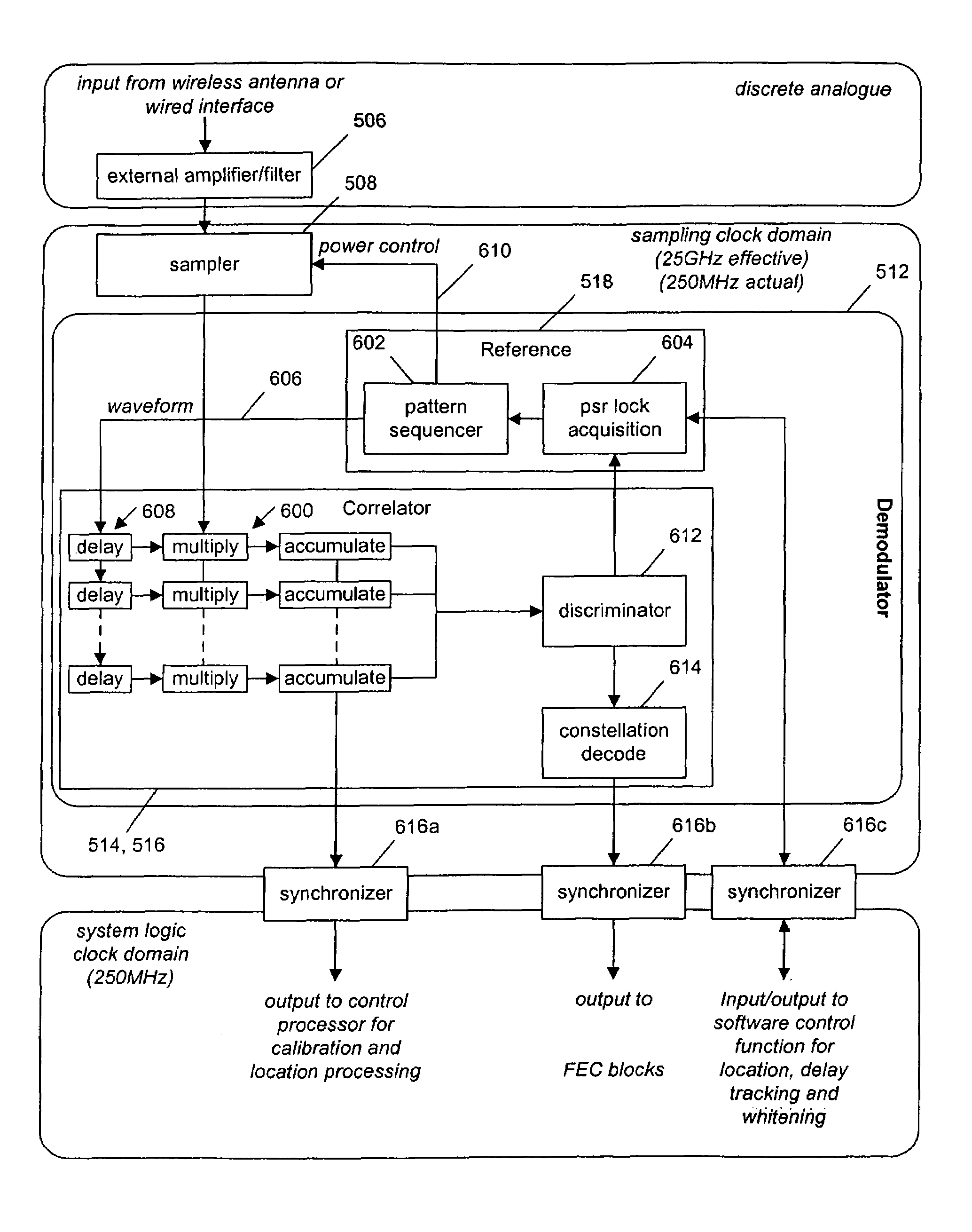
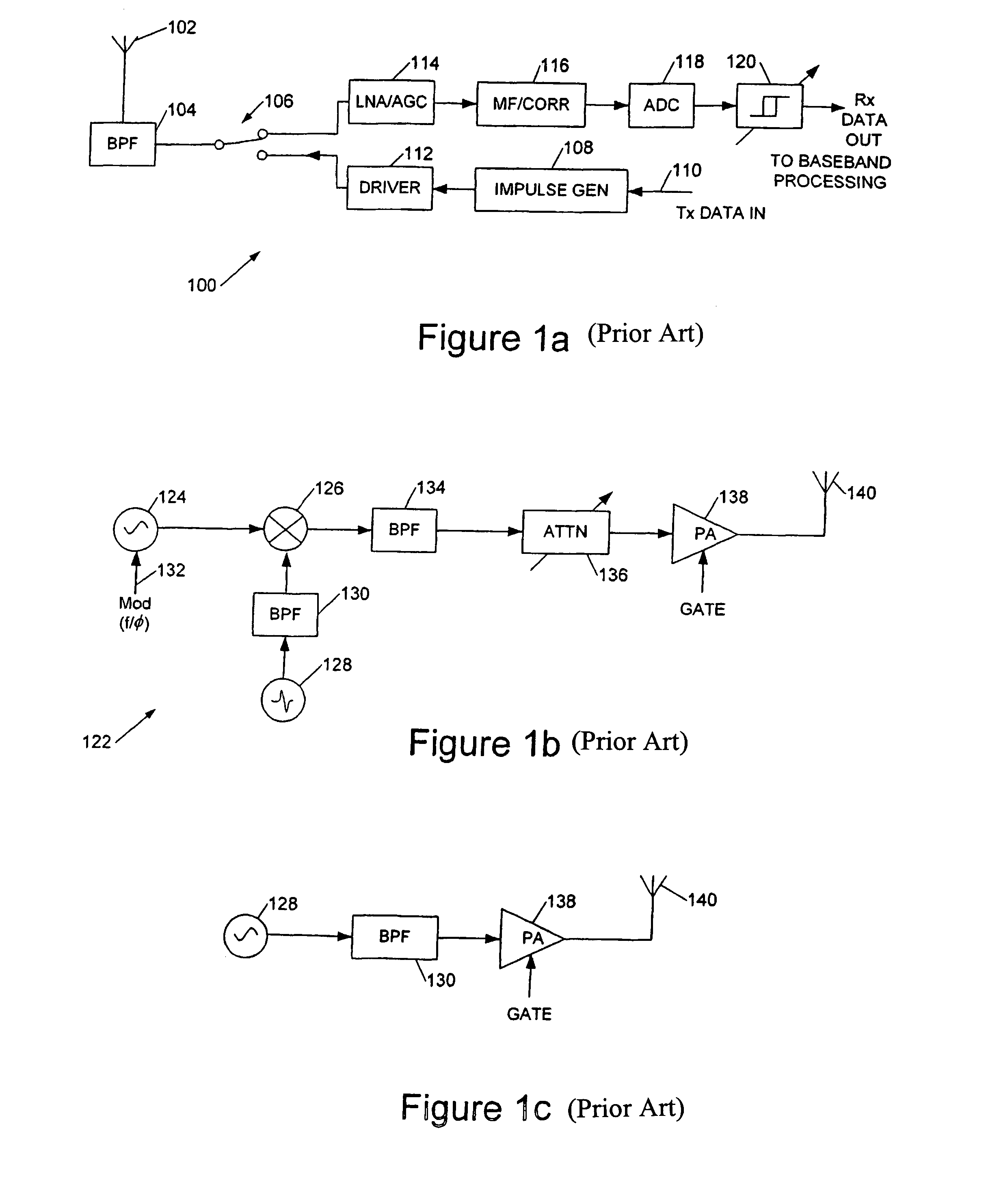
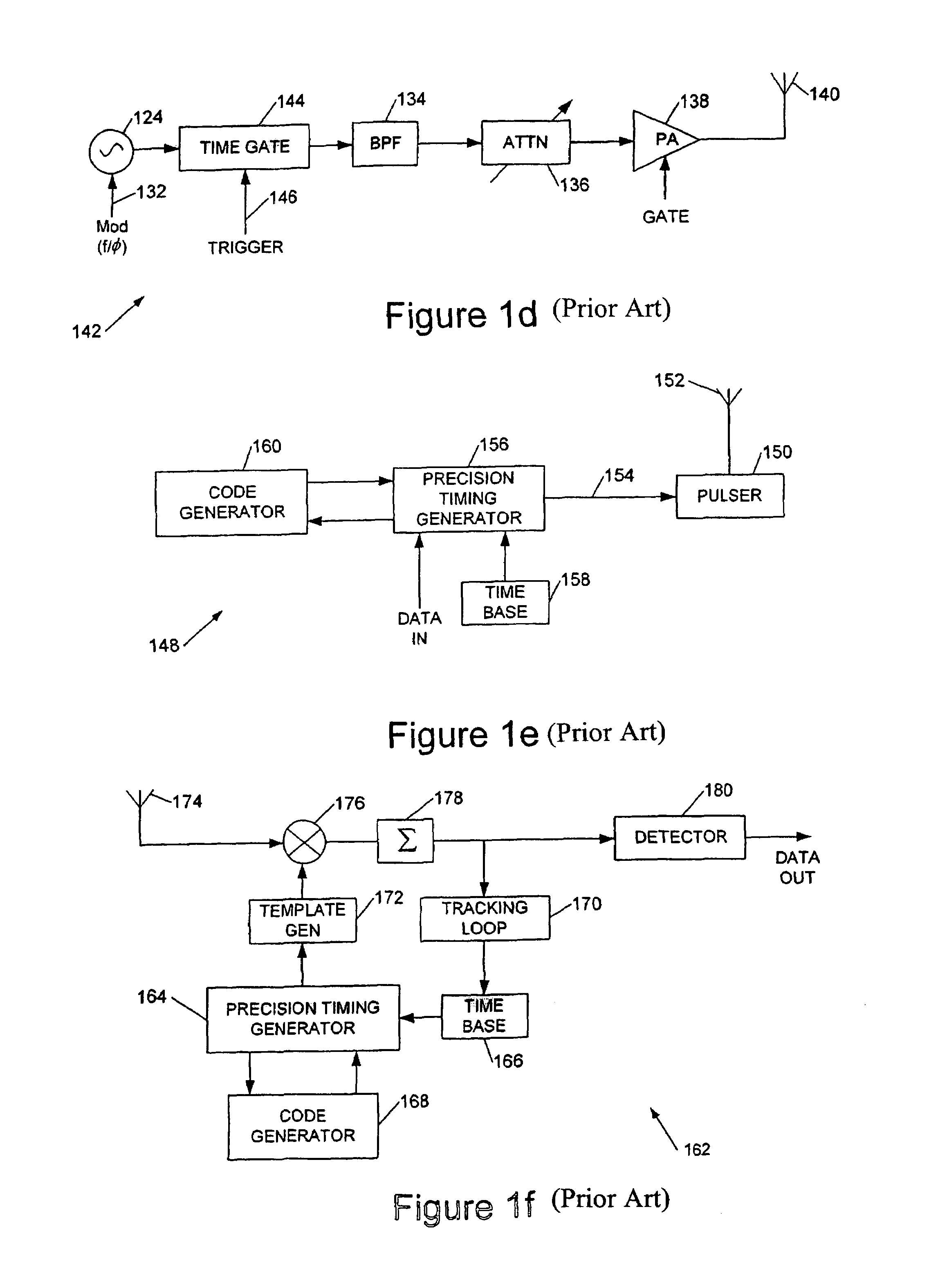
[0061]As previously mentioned a transmission medium coupling a UWB transmitter and UWB receiver will typically give rise to a number of physical effects that complicate the function of the receiver. The transmission medium may comprise a wireless or wired transmission channel. The physical effects include multiple path reflections, which result in multiple pulses at the receiver or each transmitted pulse, in some cases these pulses being phase inverted. Dispersion, frequency dependent continuation and other properties of the transmission medium distort the pulse shape. Interference and noise sources are received in addition to the desired pulse data. Noise sources include thermal noise (from the receiver itself), narrow band interference from radio transmitters sharing the same frequency spectrum, and broadband interference (from switching and alike). There may also be interference from co-located UWB systems sharing the same physical space for electrical cabling. A UWB receiver sho...


PUM


Abstract

This invention generally relates to wired and wireless ultra wideband (UWB) data communications apparatus and methods, and in particular to UWB receiver systems and architectures.An ultra wideband (UWB) receiver system comprising: a receiver front end to receive a UWB signal; an analogue-to-digital converter coupled to said receiver front end to digitize said received UBW signal; and a correlator coupled to said analogue-to-digital converter to correlate said digitized UWB signal with a reference signal.

Description

FIELD OF THE INVENTION[0001]This invention generally relates to wired and wireless ultra wideband (UWB) data communications apparatus and methods, and in particular to UWB receiver systems and architectures. The benefit of U.S. provisional 60 / 518,344 filed Nov. 10, 2003 is claimed.BACKGROUND TO THE INVENTION[0002]Techniques for UWB communication developed from radar and other military applications, and pioneering work was carried out by Dr G. F. Ross, as described in U.S. Pat. No. 3,728,632. Ultra-wideband communications systems employ very short pulses of electromagnetic radiation (impulses) with short rise and fall times, resulting in a spectrum with a very wide bandwidth. Some systems employ direct excitation of an antenna with such a pulse which then radiates with its characteristic impulse or step response (depending upon the excitation). Such systems are referred to as carrierless or “carrier free” since the resulting rf emission lacks any well-defined carrier frequency. Howev...

Claims


Application Information

Patent Timeline
Patent Type & Authority Patents(United States)
IPC IPC(8): H03D1/00H04L27/06H04B1/69
CPCH04B1/71637
Inventor BAKER, DAVIDMOORE, MARK JUSTIN
Owner TAHOE RES LTD
Why Eureka
Try Eureka