
Method and circuit for controlling an electric power plant

a technology for controlling circuits and power plants, applied in the direction of electric generator control, combined combustion mitigation, electrical apparatus, etc., can solve the problems of inability to regulate voltage by modifying excitation, unstable conditions, excessively long transients, etc., and achieve the effect of improving precision

Inactive Publication Date: 2008-12-02
STMICROELECTRONICS SRL
View PDF12 Cites 8 Cited by
  • Summary
  • Abstract
  • Description
  • Claims
  • Application Information

AI Technical Summary

Benefits of technology

This patent describes a method and control circuit for an electrical power plant that uses an asynchronous machine. The control circuit uses soft-computing techniques to adjust the capacitance and torque of the motor to ensure a constant output voltage and frequency, regardless of load conditions. This allows for precise control even when magnetic non-linearities are present. The control method improves efficiency and overcomes problems associated with using asynchronous generators in power plants. The control circuit can adjust the capacitance and torque through a switched L-C network, which can match both capacitive and inductive loads. The driver for turning on a thyristor connected to a supply line is also provided. Overall, this patent provides a solution for controlling an asynchronous machine in an efficient and precise manner.

Problems solved by technology

When the power plant is isolated from the mains, the generated voltage and frequency are not so forced and regulating them is not easy.
Moreover, it is not possible to regulate the voltage by modifying the excitation, because there is no such input in asynchronous machines.
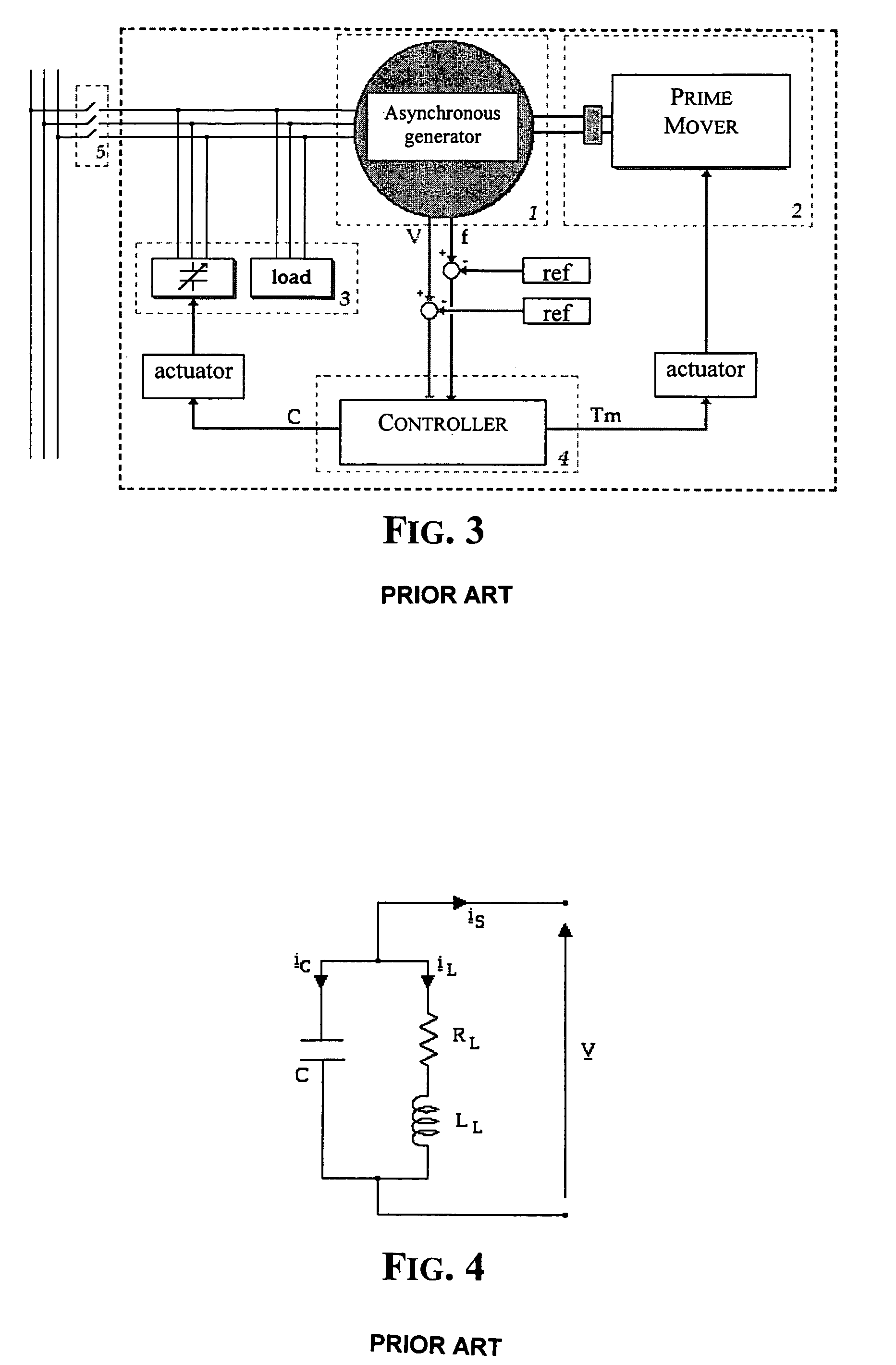
Through special studies, the Applicant found that the commonly used separate control for voltage and for frequency, as illustrated in FIG. 5, could lead to conditions of instability or to excessively long transients before reaching the desired values because of interference between the two controllers (VMAX CONTROLLER, FREQ CONTROLLER).
Moreover, such a control may not be sufficiently precise because the real system is magnetically nonlinear.

Method used


Image

  • Method and circuit for controlling an electric power plant
  • Method and circuit for controlling an electric power plant
  • Method and circuit for controlling an electric power plant

Examples


Embodiment Construction

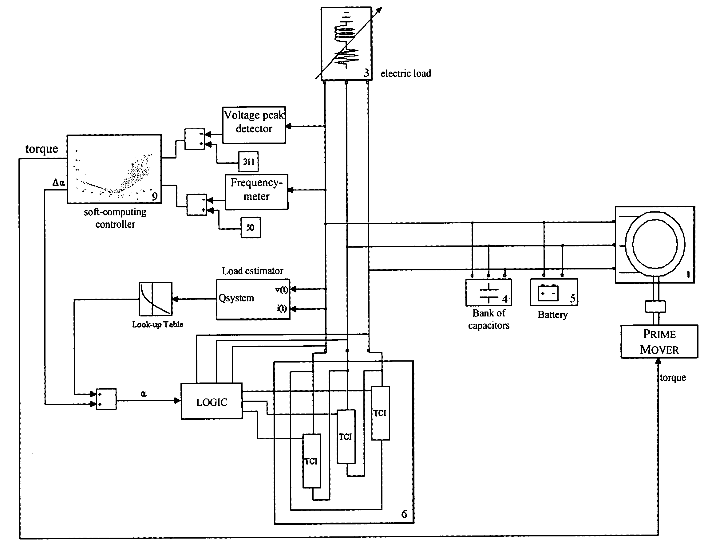
[0095]The system of this invention has a control circuit that uses soft-computing techniques based on fuzzy logic or neural networks for conjunctively processing shifts (errors) from both the requested values of generated AC voltage and frequency. From these frequency and voltage shift information, through appropriate soft-computing rules, it determines capacitance and torque values needed by the power plant for stabilizing its functioning at the desired output voltage and frequency values (for instance Vrms=220V, f=50 Hz).

[0096]The control method of this invention contemplates a voltage and frequency feedback, according to the scheme of a sample embodiment of the control circuit of this invention of FIG. 6, wherein, as for all the figures, being:[0097]Vmax ref.: the peak reference voltage (310V);[0098]frequency ref.: the reference voltage (50 Hz);[0099]Vmax: the measured peak voltage;[0100]f the “measured” (or estimated) frequency value;[0101]Vmax error: the peak voltage error;[010...


PUM


Abstract

A control circuit is for an electric power plant including an asynchronous generator of an AC voltage, a motor to rotate a rotor of the asynchronous generator as a function of a first control signal of a developed motor torque, and a bank of capacitors coupled to the asynchronous generator and having a total capacitance varying as function of a second control signal. The control circuit may include a monitor circuit to monitor at least one parameter of the AC voltage, and a control signal generator circuit cooperating with the monitor circuit to generate the first and second control signals by soft-computing techniques both as a function of the frequency and of a representative value of an amplitude of the AC voltage to make the AC voltage have a desired amplitude and frequency.

Description

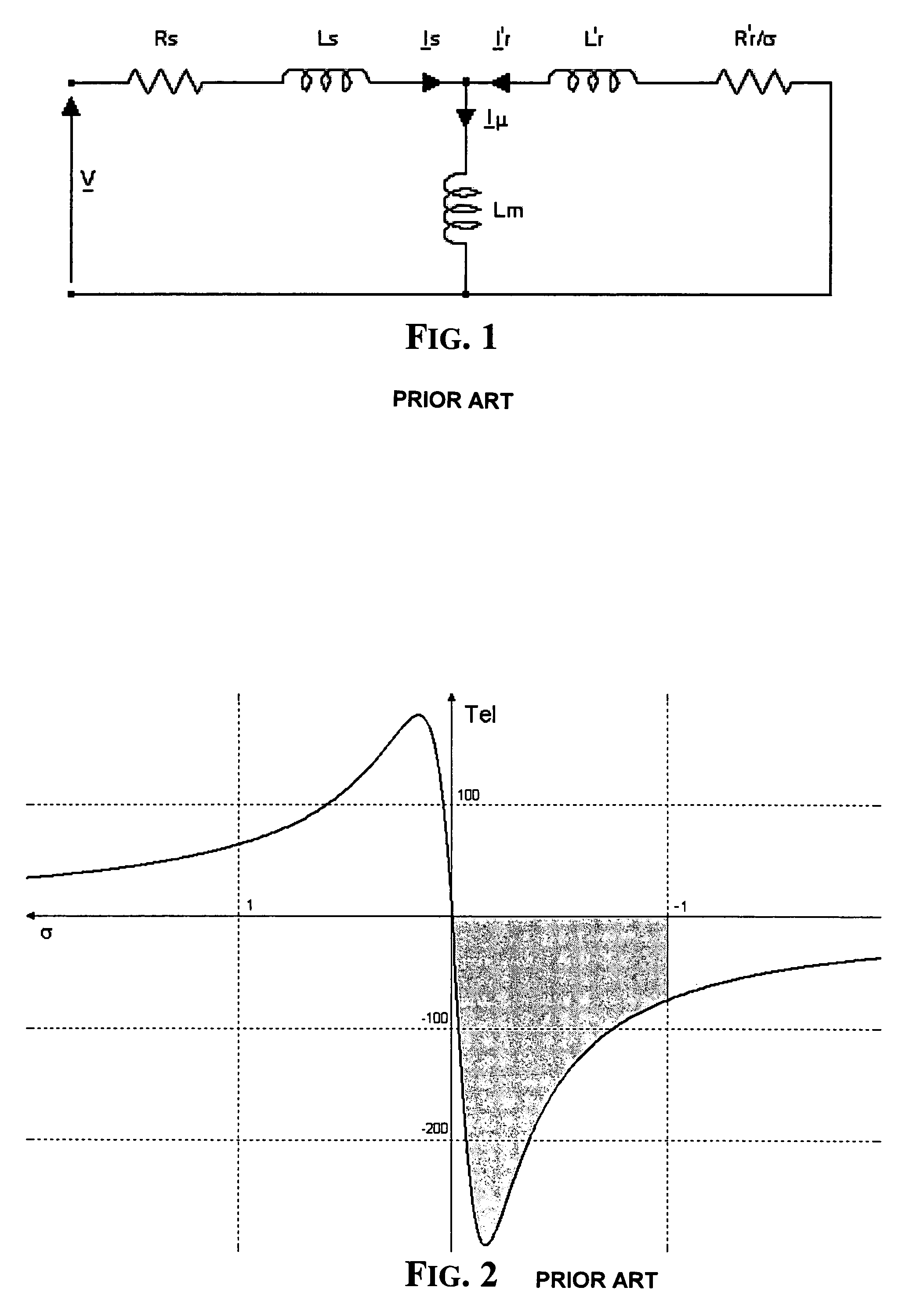
FIELD OF THE INVENTION[0001]The present invention relates to electric power plants, and, more particularly, to a method and a relative soft-computing control circuit for a power plant.BACKGROUND OF THE INVENTION[0002]Improvements in the field of power electronics and the complexity of modern control systems increase the demands of asynchronous motors in variable speed electric actuators, because of their robustness and efficiency. Traditionally asynchronous machines have been used in electric power plants, essentially in applications wherein the stator winding is connected to the distribution mains. Typical applications of asynchronous machines are in wind or water driven power plants or combined heat and power generation plants (CHP).[0003]The reasons of this traditionally restricted field of use is that asynchronous machines do not have an excitation winding and thus they require an initial magnetization for starting power generation and a reactive power source for sustaining the ...

Claims


Application Information

Patent Timeline
Patent Type & Authority Patents(United States)
IPC IPC(8): H02P11/00H02H7/06H02P9/00
CPCH02P9/30H02P9/46H02P2101/10Y02E20/14
Inventor BARATTO, STEFANOGIUFFRE, FRANCESCOMACRI, UMBERTOLAVORGNA, MARIOD'ANGELO, GIUSEPPEMOSELLI, GIOVANNI
Owner STMICROELECTRONICS SRL
Learn More