
Method for disposing material by droplet ejection, display device, method for manufacturing display device, and electronic apparatus

a technology of droplet ejection and droplet ejection, which is applied in the direction of identification means, instruments, non-linear optics, etc., can solve the problems of reducing production efficiency, reducing the yield of products, and difficulty in precisely controlling the amount of droplets, so as to reduce the effect of reducing the width of the shade portion

Inactive Publication Date: 2008-12-02
SEIKO EPSON CORP
View PDF9 Cites 11 Cited by
  • Summary
  • Abstract
  • Description
  • Claims
  • Application Information

AI Technical Summary

Benefits of technology

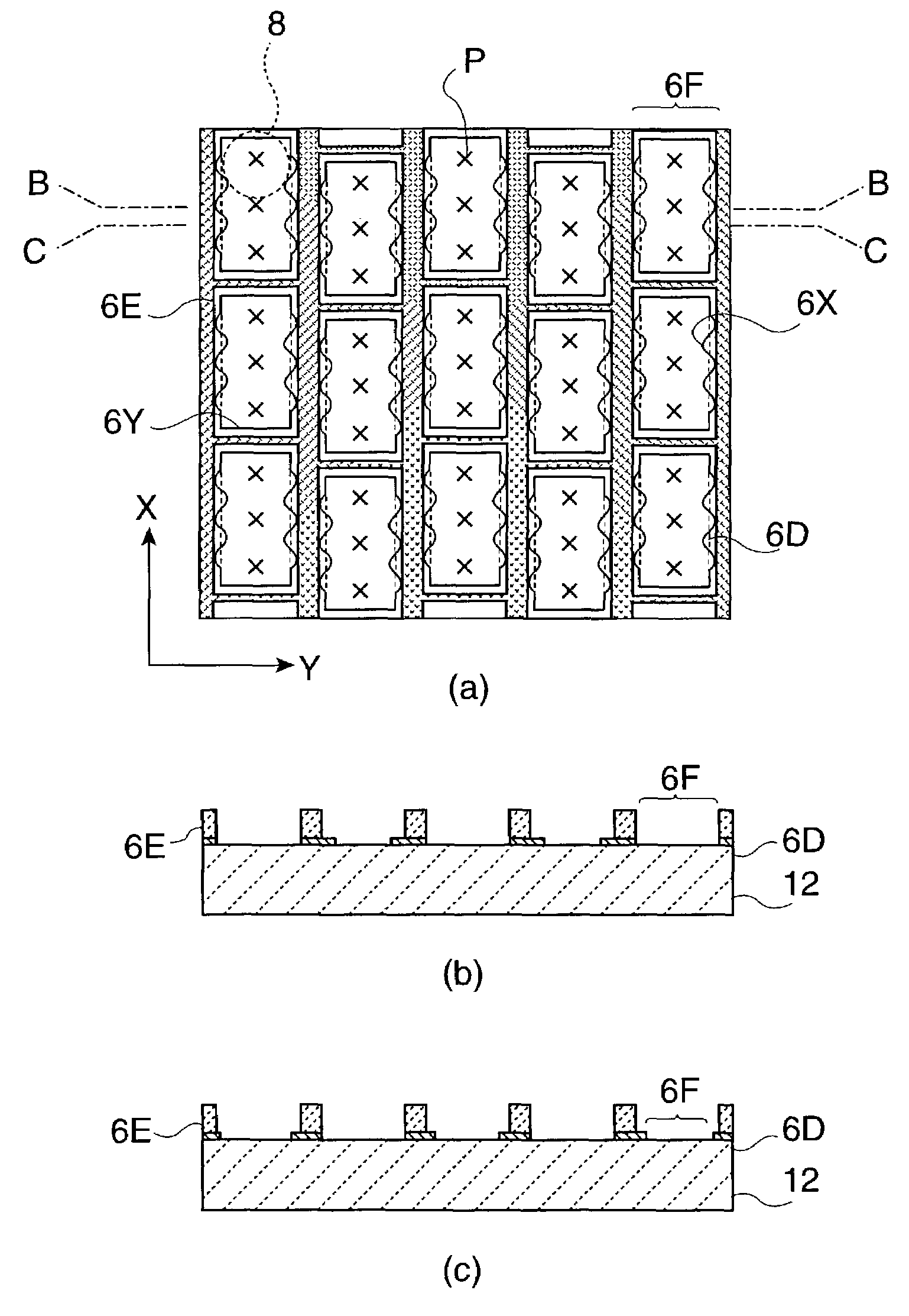
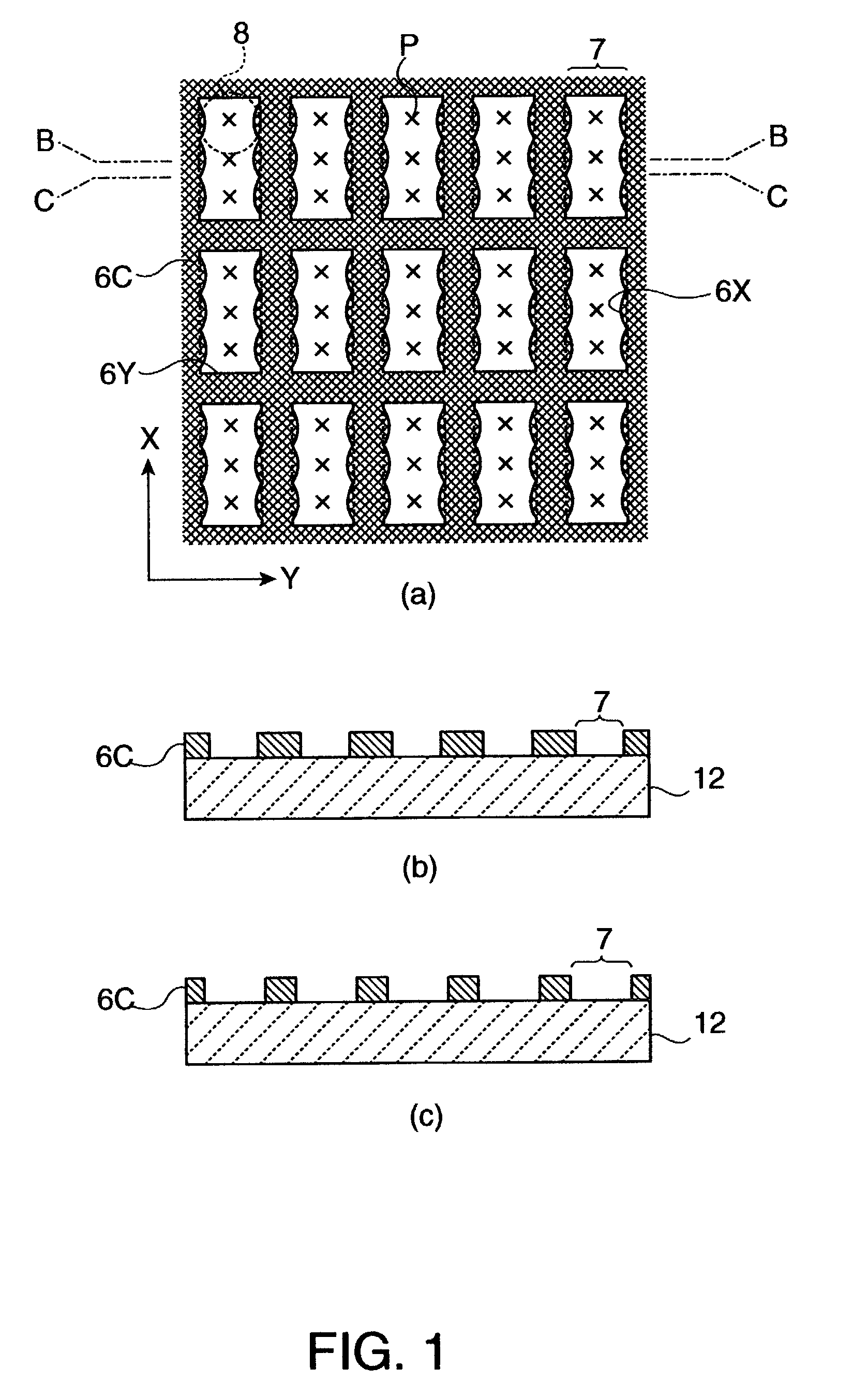
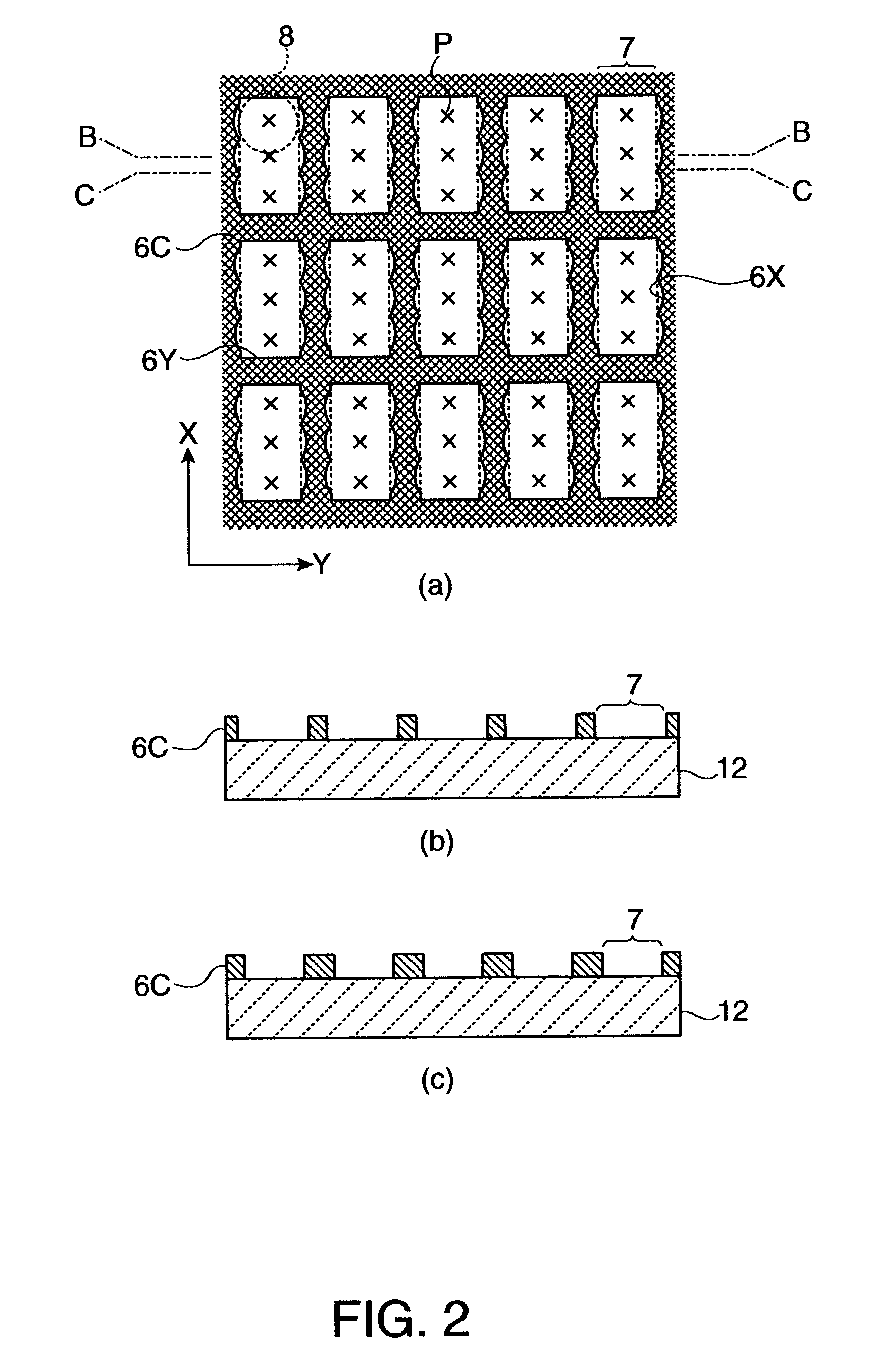
[0012]Accordingly, the present invention was made to solve the problems described above, and an object of the present invention is to provide a method for suppressing insufficient spread of droplets and mixing of droplets in neighboring regions when a liquid material in the form of droplets is ejected to a substrate. In addition, another object of the present invention is to provide a display device having the structure in which the insufficient spread of droplets and mixing thereof in neighboring regions can be suppressed and a method for manufacturing the same.
[0125]In the present invention, the display elements may be EL parts forming display dots in some cases. As the EL parts, parts emitting various colors are preferably arranged in a predetermined pattern, such as a stripe pattern, delta pattern, or mosaic pattern. In the case described above, while preventing color mixture between neighboring regions or opening portions and formation of non-colored portions in regions or opening portions, the margin for the droplet amount can be secured, and the width of the shade portion can be decreased.

Problems solved by technology

However, when a highly precise and fine display device is formed, since the amount of the droplet 8 is extremely small, it is generally difficult to precisely control the amount of the droplet, and in addition, decrease in yield of the product may occur in some cases together with decrease in production efficiency.
However, this increase may cause decrease in aperture ratio required for display devices, and as a result, a problem may occur in that it becomes difficult to realize a highly precise and fine display structure.

Method used


Image

  • Method for disposing material by droplet ejection, display device, method for manufacturing display device, and electronic apparatus
  • Method for disposing material by droplet ejection, display device, method for manufacturing display device, and electronic apparatus
  • Method for disposing material by droplet ejection, display device, method for manufacturing display device, and electronic apparatus

Examples


Embodiment Construction

[0151]Next, referring to accompanying drawings, a method for disposing a material by droplet ejection, a display device, a method for manufacturing the display device, and an embodiment of an electronic apparatus will be described in detail. Before the characteristic structure and method of the present invention are described, the structure of a color filter substrate and a manufacturing method therefor, and the structure of an EL panel and a manufacturing method therefor will first be described.

[0152]FIG. 5 shows cross-sectional views for illustrating steps (a) to (g) of a process for manufacturing a color filter substrate, and FIG. 6 is a brief flow chart showing a procedure of the process for manufacturing the color filter substrate.

[0153]First, as shown in FIG. 5(a), to a surface of a substrate 12 having light transparency formed of glass, plastic, or the like, a radiation-sensitive material 6A is applied by one of various methods, such as spin coating (rotation coating), flow c...


PUM

PropertyMeasurementUnit
thicknessaaaaaaaaaa
thicknessaaaaaaaaaa
wavelengthaaaaaaaaaa

Abstract

The invention provides a method for suppressing insufficient spread of droplets or mixing of the droplets in neighboring regions when a liquid material is disposed in the regions on a substrate by ejecting the droplets composed of the liquid material. In addition, for a display device, the structure in which insufficient spread of droplets or mixing of the droplets in neighboring regions can be suppressed and the manufacturing method therefor are provided. To accomplish the above, substantially square regions can be formed by a partition provided on a substrate. In each region, among internal surfaces and of the partition surrounding this region, the internal surfaces forming the long sides of the region have irregularities. In addition, the distance between parts of the partition opposing each other with one of regions provided therebetween is increased and decreased along the long side of the region. Furthermore, along the long side of the region, the width of the partition will be increased and decreased.

Description

BACKGROUND OF THE INVENTION[0001]1. Field of Invention[0002]The present invention relates to methods for disposing a material by droplet ejection, display devices, methods for manufacturing a display device, and electronic apparatuses. More particularly, the invention relates to the structure suitably used for a color filter or an electrooptic device and a method for manufacturing the same.[0003]2. Description of Related Art[0004]In various display devices, color filters have been generally used for performing color display. In the color filter, dot-shaped filter elements in various colors, R (red), G (green), and B (blue), are arranged on a substrate composed of glass, plastic, or the like in a predetermined pattern, such as a stripe pattern, delta pattern, or a mosaic pattern.[0005]In addition, as display devices represented by electrooptic devices, such as liquid crystal devices or EL (electroluminescent) devices, for example, there have been display devices each having the struc...

Claims


Application Information

Patent Timeline
Patent Type & Authority Patents(United States)
IPC IPC(8): H01L21/20G02B5/20B41M3/00G02B3/00G02F1/13G02F1/1333G02F1/1335G09F9/00H05B33/10H10K99/00
CPCH01L27/3246H01L27/3283H01L51/0005B41M3/003H01L51/56H10K59/122H10K59/173H10K71/135H10K71/40H10K71/00
Inventor ITO, TATSUYAKATAGAMI, SATORUKAWASE, TOMOMI
Owner SEIKO EPSON CORP
Learn More