
Recording and/or reproducing apparatus with an optical pickup actuator having high thrust

a technology of optical pickup actuator and recording apparatus, which is applied in the field of recording and/or reproducing apparatus with optical pickup actuator having high thrust, can solve the problems of increasing the ac sensitivity by reducing the weight of the optical pickup actuator, affecting the quality of the recording apparatus, and affecting the quality of the recording. , to achieve the effect of sufficient thrust and good linearity

Inactive Publication Date: 2008-11-18
TOSHIBA SAMSUNG STORAGE TECH KOREA CORP
View PDF15 Cites 2 Cited by
  • Summary
  • Abstract
  • Description
  • Claims
  • Application Information

AI Technical Summary

Benefits of technology

[0009]Accordingly, embodiments of the present invention, at least as discussed herein, set forth a magnetic driving unit capable of driving an optical pickup actuator, e.g., in a recording and / or reproducing apparatus, in a tilting direction with good linearity and with sufficient thrust.
[0010]Further, embodiments of the present invention also set forth an optical pickup actuator, e.g., in a recording and / or reproducing apparatus, having a high AC sensitivity suitable for high capacity recording media, such as high-speed blue-ray discs (BDs) or high-speed HD-DVDs, by increasing the thrust of a magnetic driving unit.

Problems solved by technology

So, increasing the AC sensitivity by reducing the weight of the optical pickup actuator may not be fruitful.
Consequently, to achieve fast recording / reproduction, optical pickup actuators for BDs or HD-DVDs, for example, must have increased thrust, since the option of reducing the weight may be difficult.
However, in many cases, when optical pickup actuators for such high capacity recording media are designed, the corresponding magnetic driving units do not generate sufficient strong thrust, or the thrust may be sufficient, but tilting becomes impossible.

Method used


Image

  • Recording and/or reproducing apparatus with an optical pickup actuator having high thrust
  • Recording and/or reproducing apparatus with an optical pickup actuator having high thrust
  • Recording and/or reproducing apparatus with an optical pickup actuator having high thrust

Examples


Embodiment Construction

[0037]Reference will now be made in detail to embodiments, at least as discussed herein, of the present invention, examples of which are illustrated in the accompanying drawings, wherein like reference numerals refer to the like elements throughout. Embodiments are described below to explain the present invention by referring to the figures.

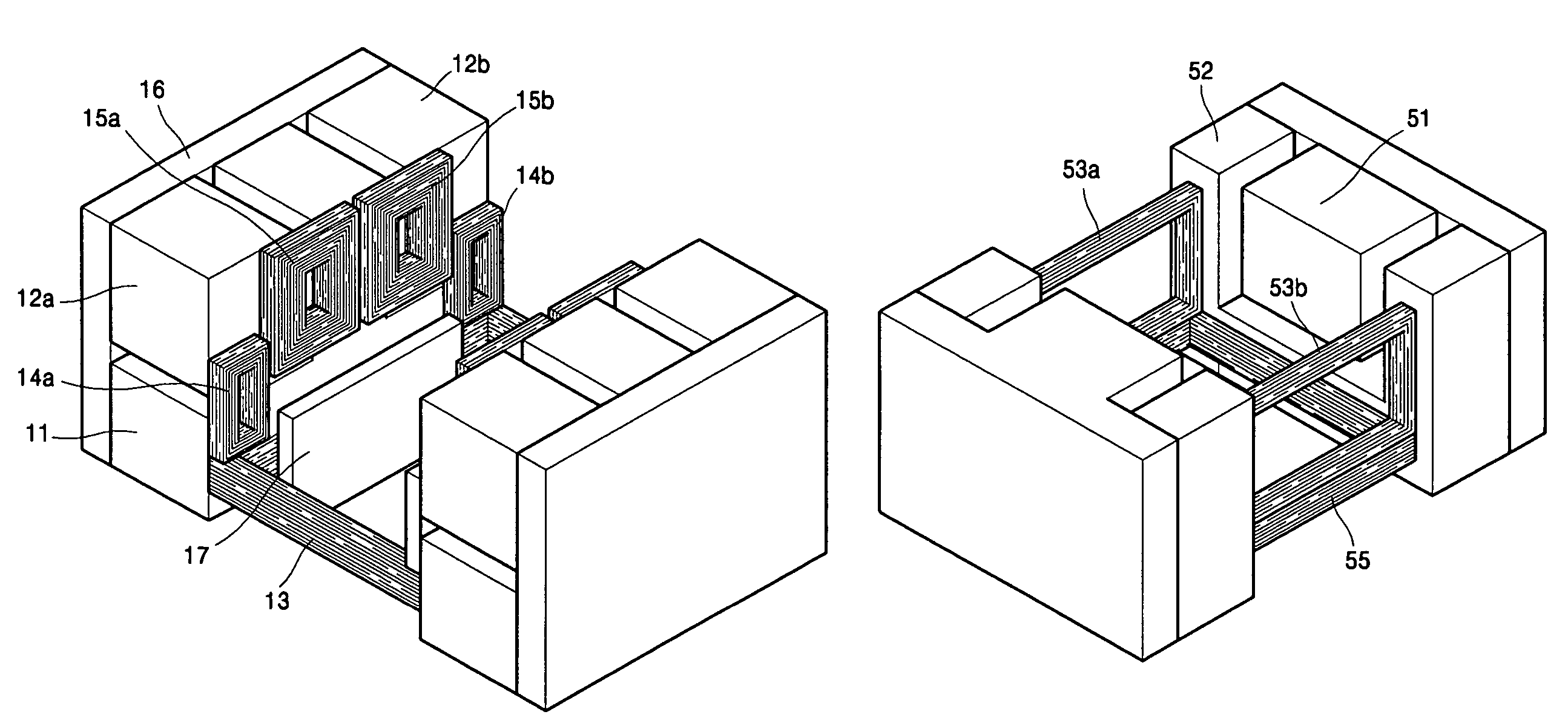
[0038]Accordingly, FIGS. 2A and 2B illustrate configurations of magnets and coils, respectively, of a magnetic driving unit in an optical pickup actuator, according to an embodiment of the present invention. As shown in FIG. 2A, a single magnet driving surface of the magnetic driving unit may include a first magnet 12a and a second magnet 12b, disposed parallel to each other, and a third magnet 11 disposed between the first and second magnets 12a and 12b while surrounding bottom sides thereof. The first and second magnets 12a and 12b may have rectangular shapes, and the third magnet 11 may have a convex shape, for example.

[0039]Here, the first an...


PUM


Abstract

An optical recording and / or reproducing apparatus with an optical pickup actuator having high thrust. The optical pickup actuator may include a lens holder which holds an objective lens and is movably supported by a supporting unit, and a magnetic driving unit which drives the lens holder in a focusing direction, a tracking direction, and / or a tilting direction. The magnetic driving unit includes a surface-triple pole magnet portion and a coil portion. The surface-triple pole magnet portion has a plurality of polarized, i.e., differently magnetized, areas formed by facing sides of two magnets among three magnets. The coil portion includes tracking coils and tilt coils disposed to interact with the polarized areas of the surface-triple pole magnet portion and a focusing coil disposed to interact with a non-polarized area of the surface-triple pole magnet portion.

Description

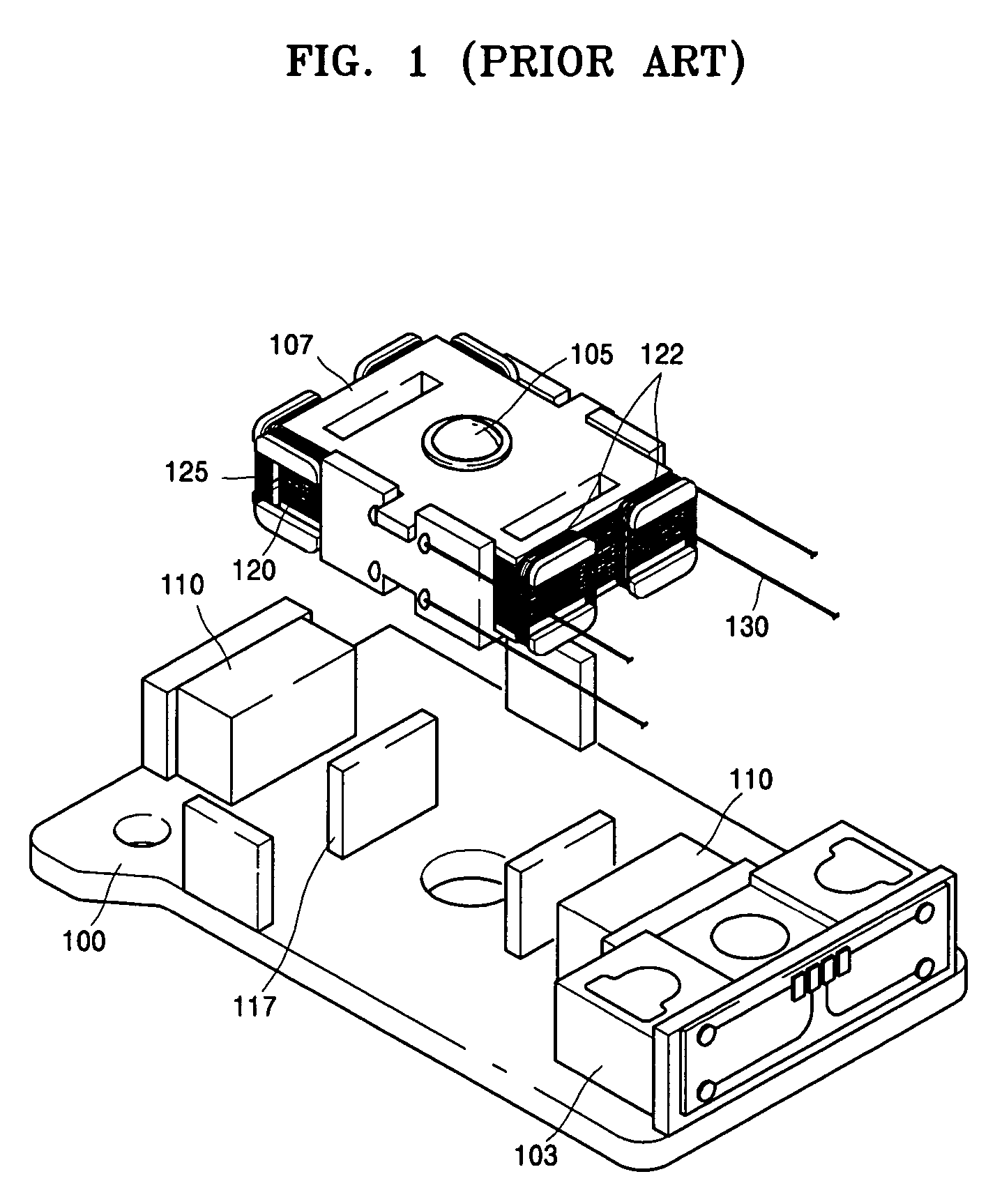
CROSS-REFERENCE TO RELATED APPLICATIONS[0001]This application claims the priority benefit of Korean Patent Application No. 10-2005-0024956, filed on Mar. 25, 2005, in the Korean Intellectual Property Office, the disclosure of which is incorporated herein in its entirety by reference.BACKGROUND OF THE INVENTION[0002]1. Field of the Invention[0003]Embodiments of the present invention, at least as discussed herein, relate to a recording and / or reproducing apparatus with an optical pickup actuator having high thrust, and more particularly, to a recording / reproducing apparatus with an optical pickup actuator having high thrust and alternating current (AC) sensitivity suitable for high capacity recording media, such as blue-ray discs (BDs) or HD-DVDs.[0004]2. Description of the Related Art[0005]An optical pickup actuator in an optical recording / reproducing apparatus records and / or reproduces information to / from an optical recording medium, e.g., mounted on a turntable, that is, the record...

Claims


Application Information

Patent Timeline
Patent Type & Authority Patents(United States)
IPC IPC(8): G02B7/02
CPCG11B7/0933G11B7/0935G11B7/0932G11B7/0956A47G1/06
Inventor JANG, DAE-JONGSONG, BYUNG-YOUNLEE, YOUNG-BINRYOO, BYUNG-RYULSEONG, PYONG-YONGLEE, YOUNG-WON
Owner TOSHIBA SAMSUNG STORAGE TECH KOREA CORP
Learn More