
Ethernet passive optical network for convergence of broadcasting and communication

a technology of passive optical network and broadcasting, applied in the direction of data switching network, multiplex communication, star/tree network, etc., to achieve the effect of high capacity, high speed and high quality

Inactive Publication Date: 2008-11-11
SAMSUNG ELECTRONICS CO LTD
View PDF11 Cites 4 Cited by
  • Summary
  • Abstract
  • Description
  • Claims
  • Application Information

AI Technical Summary

Benefits of technology

[0017]The present invention has been made to solve the above-mentioned problems occurring in the prior art, and an object of the present invention is to provide an Ethernet passive optical network for convergence of broadcasting and communication, which can provide a user with high capacity and high speed communication data in addition to real time digital broadcasting / image signals of high quality.
[0018]It is another object of the present invention to provide an Ethernet passive optical network, in which an OLT selects broadcasting channels required by subscribers and transmits the selected channels to an ONT. Advantageously, the Ethernet passive optical network therefore need not employ an EDFA for multiple broadcastings or incur the concomitant expense. As a further consequence and benefit, the ONT can employ a low-price optical receiver meeting relatively low-quality specifications.
[0019]It is a further object of the present invention to provide an Ethernet passive optical network, in which a quality of service (QoS) can be secured in transmitting not only digital broadcasting but also a digital image of high quality which will be required by subscribers in the future.

Problems solved by technology

Advantageously, the Ethernet passive optical network therefore need not employ an EDFA for multiple broadcastings or incur the concomitant expense.

Method used


Image

  • Ethernet passive optical network for convergence of broadcasting and communication
  • Ethernet passive optical network for convergence of broadcasting and communication
  • Ethernet passive optical network for convergence of broadcasting and communication

Examples


Embodiment Construction

[0026]Hereinafter, a preferred embodiment according to the present invention will be described with reference to the accompanying drawings. In the following description of the present invention, details of known functions and configuration incorporated herein will be omitted for clarity of presentation.

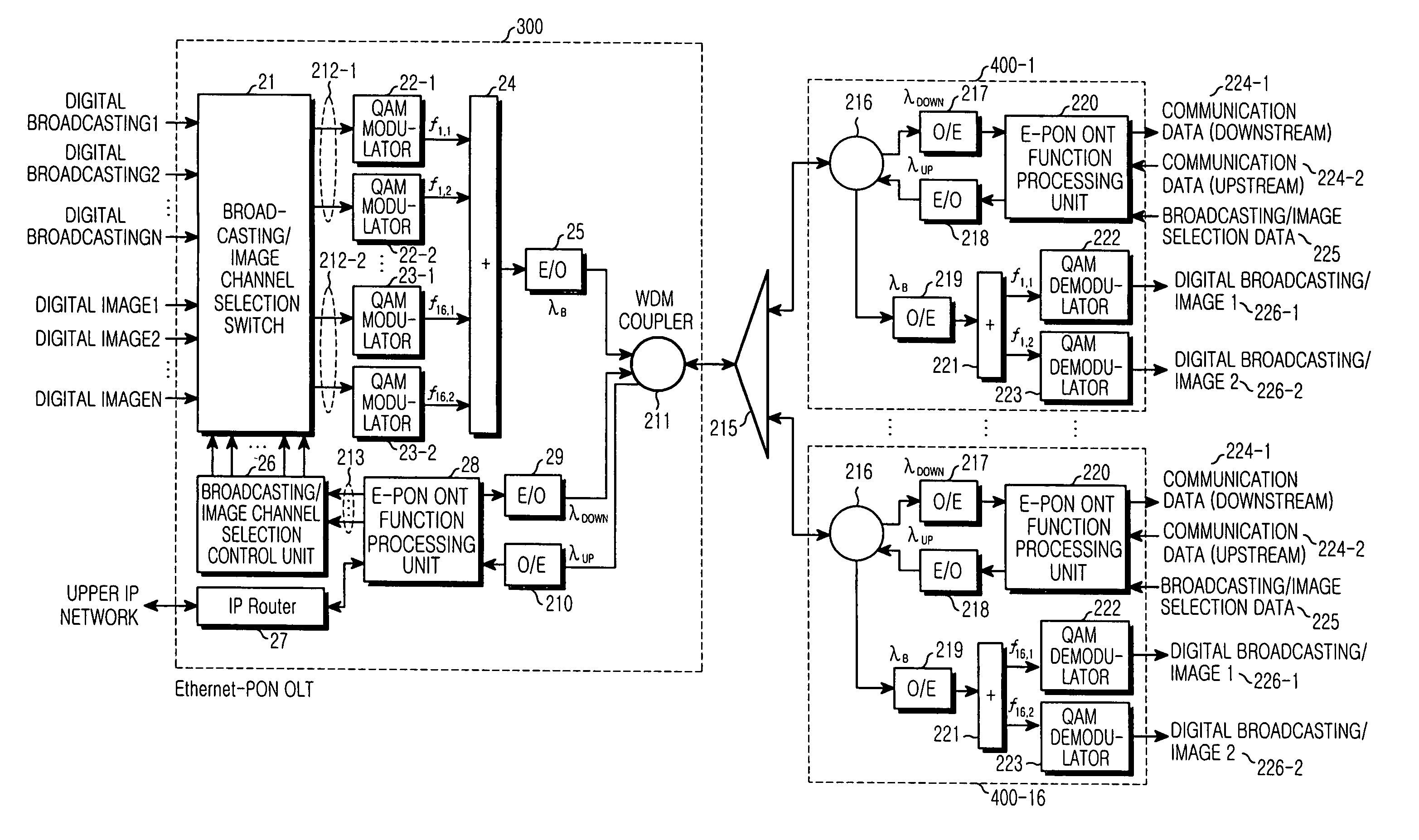
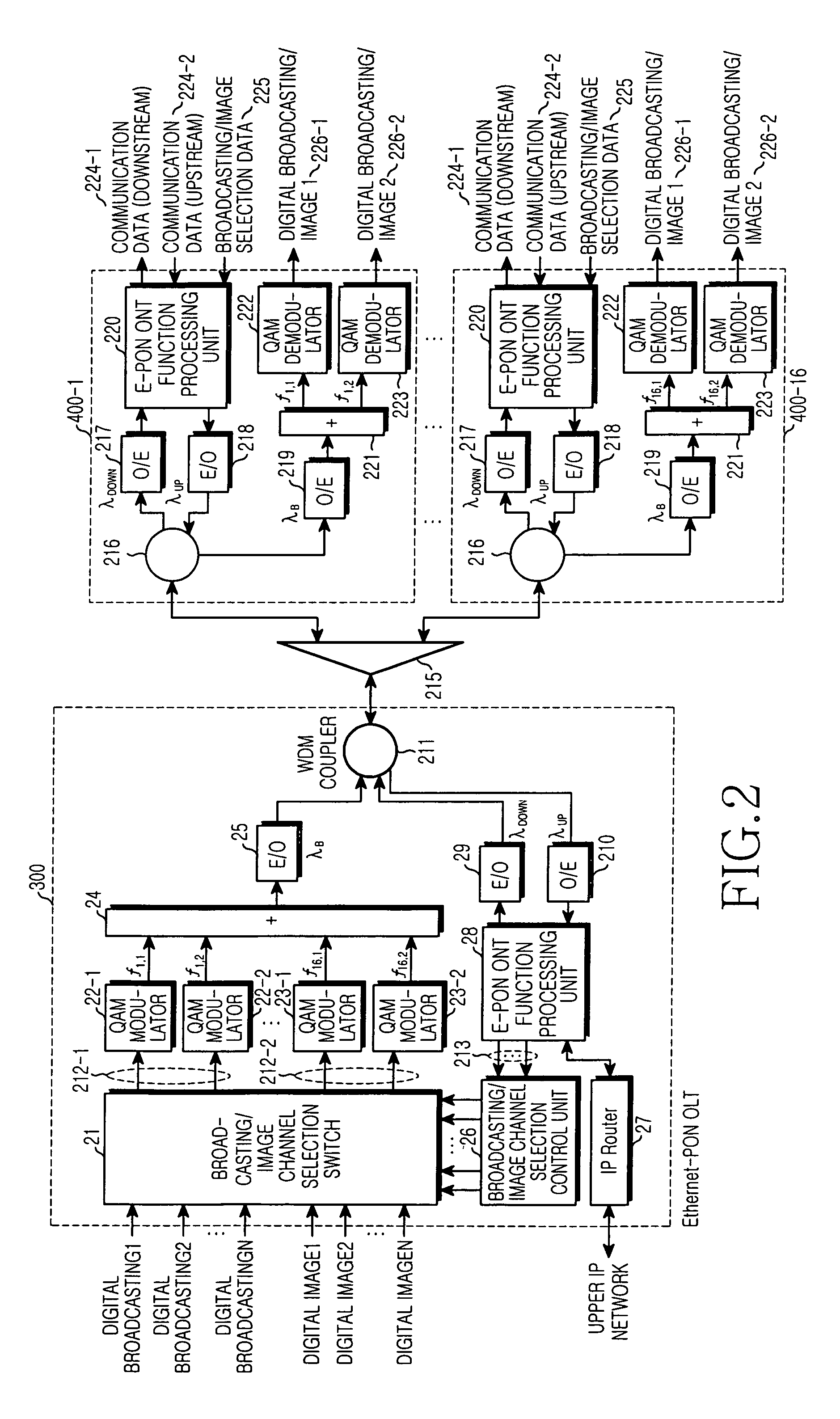
[0027]FIG. 2 shows, by way of illustrative and non-limitative example, a block diagram of an Ethernet passive optical network (hereinafter, referred to as EPON) for convergence of broadcasting and communication according to an embodiment of the present invention.

[0028]The EPON according to the present invention includes one OLT 300, an optical divider 215 and 16 ONTs 400-1 to 400-16. Each of ONTs 400-1 to 400-16 is assigned to a respective user. The OLT 300 includes a broadcasting / image channel selecting switch 21, a broadcasting / image channel selection control unit 26, quadrature amplitude modulation (hereinafter, referred to as QAM) modulators 22-1 to 22-32, a combiner 24, an optica...


PUM


Abstract

An EPON for providing a subscriber with a high speed / high capacity data service and a real time digital broadcasting / image service includes an OLT for switching digital broadcasting / image data according to broadcasting / image selection information from each ONT, modulating the switched data into frequencies assigned to each ONT, coupling a broadcasting / image signal with a communication signal, and transmitting the coupled signal. The digital broadcasting / image data is transmitted from an outside broadcaster, the broadcasting / image signal is a combination of the modulated signals, and the communication signal is obtained by optically modulating communication data from an IP network. Further included in the EPON are multiple ONTs, and a divider for dividing the signal from the OLT for routing to each of the multiple ONTs, combining signals from the multiple ONTs, and transmitting the combined signal to the OLT.

Description

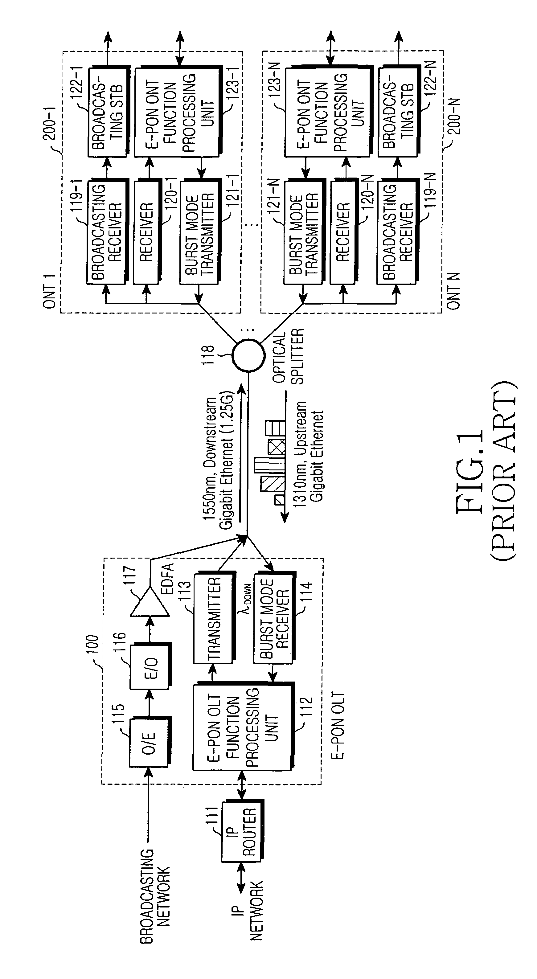
CLAIM OF PRIORITY[0001]This application claims priority to an application entitled “Ethernet passive optical network for convergence of broadcasting and communication,” filed in the Korean Intellectual Property Office on Jun. 30, 2003 and assigned Serial No. 2003-43846, the contents of which are hereby incorporated by reference.BACKGROUND OF THE INVENTION[0002]1. Field of the Invention[0003]The present invention relates to an apparatus for serving a CAS broadcasting encrypted in various ways in a convergence system of broadcasting and communication.[0004]2. Description of the Related Art[0005]In order to effectively provide subscribers with a high speed / high capacity data service and a real time digital broadcasting / image service, data must be transmitted at a speed of more than 100 Mbps. However, such a high speed / high capacity data service and a real time digital broadcasting / image service cannot be provided by means of digital subscriber line (DSL) or a cable modem, which have at...

Claims


Application Information

Patent Timeline
IPC IPC(8): H04L12/56H04L12/44H04B10/00H04B10/27H04B10/272H04J14/00H04J14/02H04L12/28H04Q11/00
CPCH04J14/0226H04J14/0282H04Q11/0067H04J14/0232H04J14/0247H04J14/0252H04J14/0298H04Q11/0066H04L12/28
Inventor LEE, KI-CHEOLOH, YUN-JEPARK, TAE-SUNGKOH, JUN-HO
Owner SAMSUNG ELECTRONICS CO LTD
Learn More