Tire balancing apparatus

a technology of balancing apparatus and tires, which is applied in the direction of measurement devices, structural/machine measurement, instruments, etc., can solve the problems of inability to test the size of tires/wheel assemblies, unacceptably long cycle times of machines, and considerable downtime, so as to reduce the maintenance of spindle assemblies and improve reliability.

Inactive Publication Date: 2008-11-11
MICRO POISE MEASUREMENT SYST
View PDF21 Cites 16 Cited by
  • Summary
  • Abstract
  • Description
  • Claims
  • Application Information

AI Technical Summary

Benefits of technology

[0008]According to another feature of the invention, the frame structure for the machine includes three spaced apart ground engaging support members which together form a three point support arrangement for the machine. This support arrangement increases stability of the machine. In the illustrated embodiment, each support member includes a stud, the lower end of which terminates in a cone-shaped surface. The cone-shaped surface is received in a complementally-shaped surface recess formed in a ground engaging receiver member.
[0013]According to another feature of the invention, the disclosed spindle assembly includes a shaft assembly that is rotatably supported by a bearing arrangement located within a bearing housing. A clamping mechanism for engaging a tire or a tire / wheel assembly to be rotated is located at an upper end of the shaft assembly; whereas the bearing housing is located below the clamping mechanism. A drive motor including a drive motor housing and an armature is operative to drivingly rotate the shaft assembly. The armature is coupled to the shaft assembly, such that the armature is maintained in its operative position within the motor housing by the bearing arrangement that rotatably supports the shaft assembly. With the present invention, separate drive motor bearings that would ordinarily be located between the motor housing and the armature are eliminated. This reduces maintenance of the spindle assembly and improves its reliability.

Problems solved by technology

For at least some types of currently available machines, the tire / wheel assembly size that can be tested is limited.
In other types of machines, considerable downtime is encountered when the machine needs to be adjusted for a different size tire / wheel.
Still other machines have unacceptably long cycle times and, as a result, have a low throughput.

Method used


Image

  • Tire balancing apparatus
  • Tire balancing apparatus
  • Tire balancing apparatus

Examples


Embodiment Construction

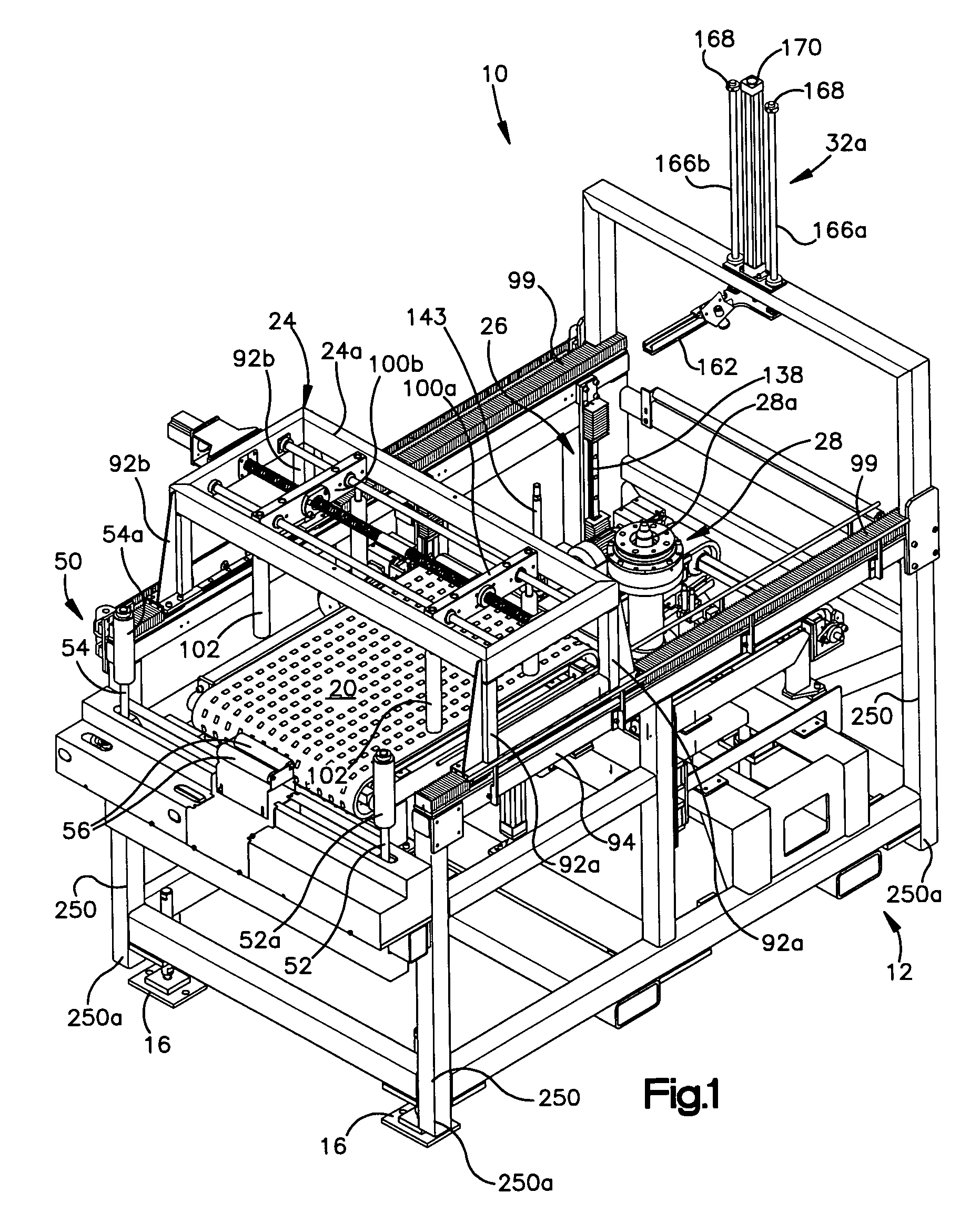
[0037]FIG. 1 illustrates the overall construction of a dynamic balancing machine 10 for determining balance (or imbalance) conditions in a tire / wheel assembly. Referring also to FIGS. 2 and 3, the machine 10 includes a base indicated generally by the reference character 12 that is supported on a plant floor via support members 16 that form a three point or triangular support system (shown best in FIG. 3).

[0038]The machine includes an entrance conveyor 20 and a tire shuttle 24 which through coordinated movement with the conveyor 20 delivers a tire / wheel assembly 22 (shown in FIG. 4C) to a balancing test station indicated generally by the reference character 26; the balancing test station 26 includes a rotatable spindle 28a forming part of a spindle assembly 28. The machine also includes upper and lower tire marking mechanisms indicated generally by the reference characters 32a, 32b, respectively (see FIG. 2). At the conclusion of the balancing test cycle, an exit conveyor indicated g...


PUM


Abstract

A machine and method for performing balancing measurements on a tire or tire / wheel assembly that includes a structure defining spaced apart tire centering and tire testing positions. A first conveyor moves a tire to a centering position where a shuttle assembly is operative to center the tire and, after it has been centered, engages the tire and effects the transfer of the tire from the centering station to a testing station. The shuttle assembly includes a pair of grippers that move towards and away from each other, in a lateral direction in order to engage the tire. The first conveyor permits movement of the tire in a lateral direction; whereas it substantially resists relative movement between the tire and conveyor in the longitudinal direction, i.e., the direction of movement of the conveyor. The shuttle assembly is mounted for movement in a longitudinal direction and includes a drive mechanism which allows the shuttle assembly to move relative to a tire in a longitudinal direction as the grippers engage the tire so that the shuttle assembly can align itself, in the longitudinal direction with respect to the tire. The frame structure of the machine includes three spaced apart support members providing a three point support arrangement for the machine. The machine also includes at least four legs which extend downwardly, but are spaced above a plane defined by the support members and inhibit tipping of the machine beyond predetermined limits. The testing station which includes a spindle assembly for rotating the tire also includes an elevator mechanism for lowering the tire on to the spindle and for raising the tire off the spindle. A lower marking mechanism forms part of the elevator and is operative to mark a predetermined location on the tire at the conclusion of a tire testing procedure. The spindle assembly includes a drive motor comprised of a drive motor housing and an armature. The armature is maintained in its operative position by a bearing arrangement associated with a shaft assembly forming part of the spindle assembly which eliminates the need for armature supporting bearings in the drive motor housing.

Description

TECHNICAL FIELD[0001]The present invention relates generally to the balancing of tire / wheel assemblies and, in particular, to a method and apparatus for determining the locations and amount of corrective wheel weights that need to be installed on a tire / wheel assembly to correct an imbalance condition.BACKGROUND ART[0002]Tire / wheel assemblies are typically balanced by vehicle manufacturers prior to the installation of the tire assemblies on the vehicle. Equipment for testing the balance of tire / wheel assemblies is currently available. These testing machines generally comprise a spindle that rotates the tire / wheel assembly. The spindle is coupled to force sensors, such as load cells, which provide signals that are used to determine the location and amount of wheel weights required to correct an imbalance condition in the tire assembly. Typically, the locations where wheel weights are to be installed are marked on the tire and / or wheel. The marked wheel is then conveyed to a weight ap...

Claims


Application Information

Patent Timeline
Patent Type & Authority Patents(United States)
IPC IPC(8): G01M1/16G01M1/02G01M1/06G01M1/22G01M1/32
CPCG01M1/045G01M1/06G01M1/225
Inventor WILLIAMS, THOMAS D.HAYDU, STEVEHALL, RONALD JANWATSON, STEVESHAFFER, BILLNEHRENZ, NEALBEEBE, JAMES
Owner MICRO POISE MEASUREMENT SYST
Why Eureka
Try Eureka