Workpiece clamp

a workpiece and clamping technology, applied in the field of workpiece clamping, can solve the problems of reducing yield, affecting the production efficiency of semiconductor/solid-state devices, and affecting the production efficiency of semiconductors, so as to achieve the effect of reducing maintenance costs, reducing production costs, and significantly reducing the inner ring shi

Inactive Publication Date: 2016-11-24
EPISIL TECH INC
View PDF3 Cites 0 Cited by
  • Summary
  • Abstract
  • Description
  • Claims
  • Application Information

AI Technical Summary

Benefits of technology

The present invention is an improved workpiece clamp that solves the problem of peripheral indent issues in the prior art. The design features flat portions in the inner ring of the clamp with a specific angle between them. This reduces inner ring shift, reduces abnormal products, lowers maintenance costs, and improves machine stability.

Problems solved by technology

However, when the wafer clamp of the deposition machine shifts, the abnormal peripheral indent occurs.
Therefore, the wafer deposition performance is deteriorated and the yield is reduced.

Method used


Image

  • Workpiece clamp
  • Workpiece clamp
  • Workpiece clamp

Examples


Embodiment Construction

[0027]Reference will now be made in detail to the present preferred embodiments of the invention, examples of which are illustrated in the accompanying drawings. Wherever possible, the same reference numbers are used in the drawings and the description to refer to the same or like parts.

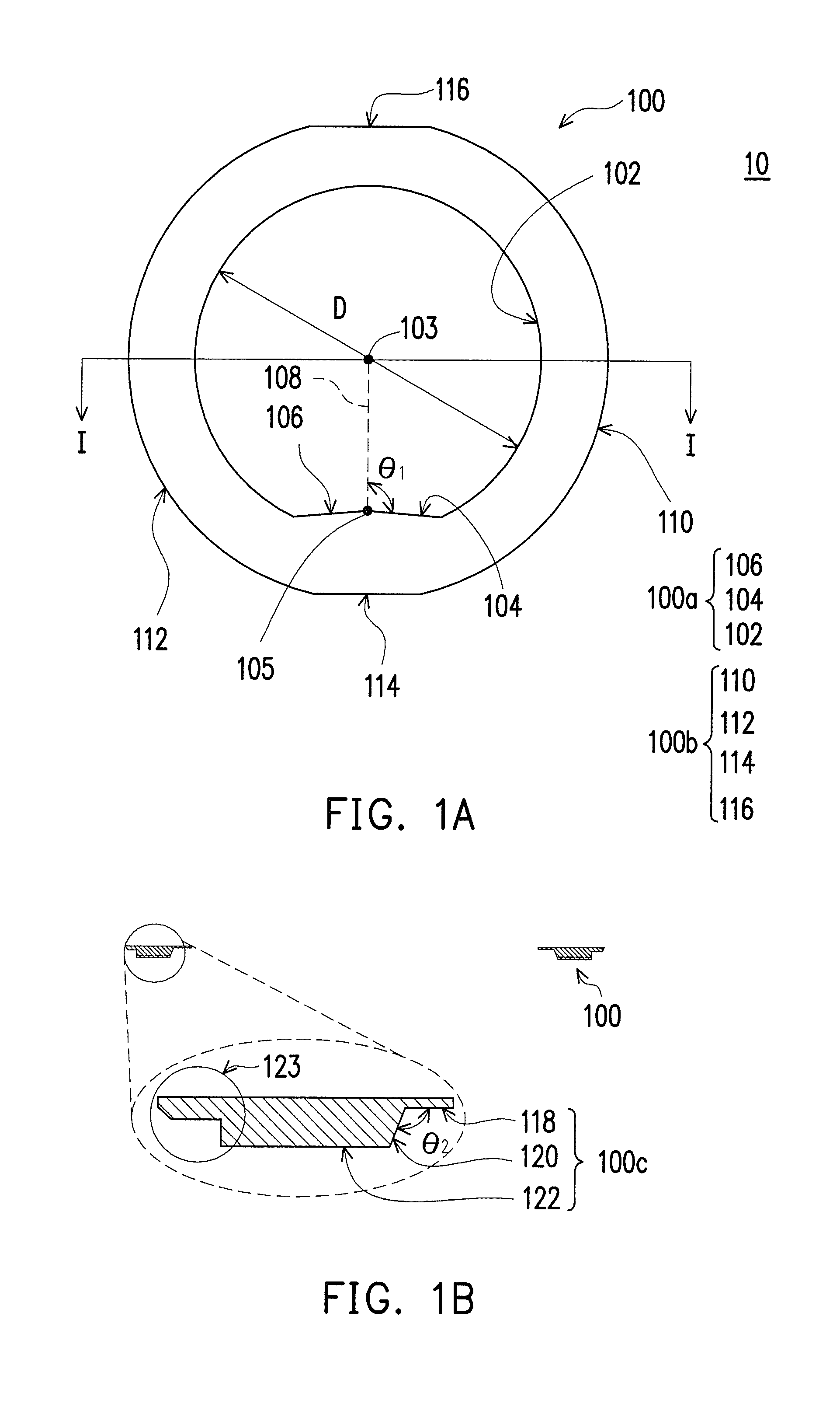
[0028]FIG. 1A is a top view of an inner ring of a workpiece clamp according to an embodiment of the present invention. FIG. 1B is a cross-sectional view of the inner ring taken along the line I-I of FIG. 1A with an enlarged local view illustrated below.

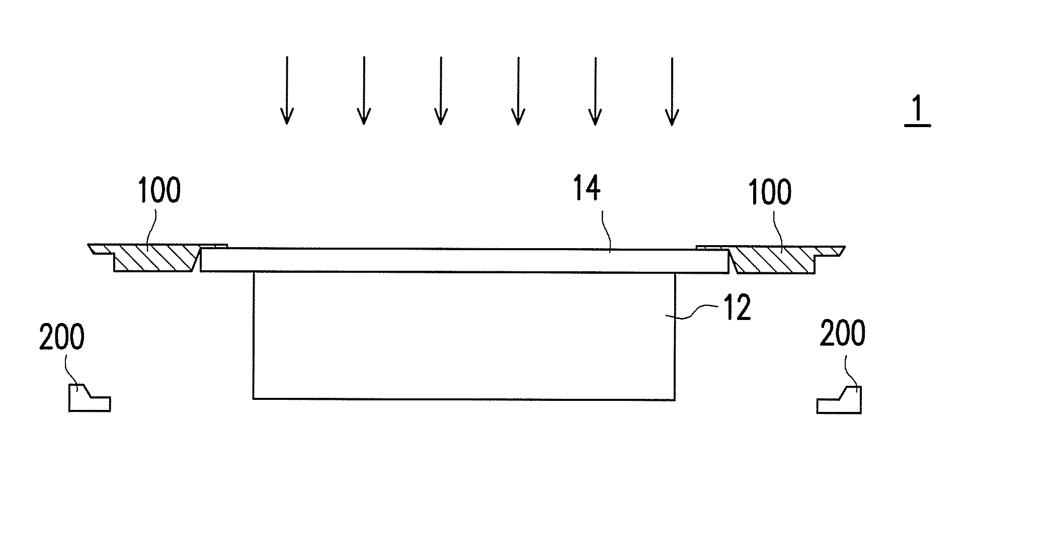
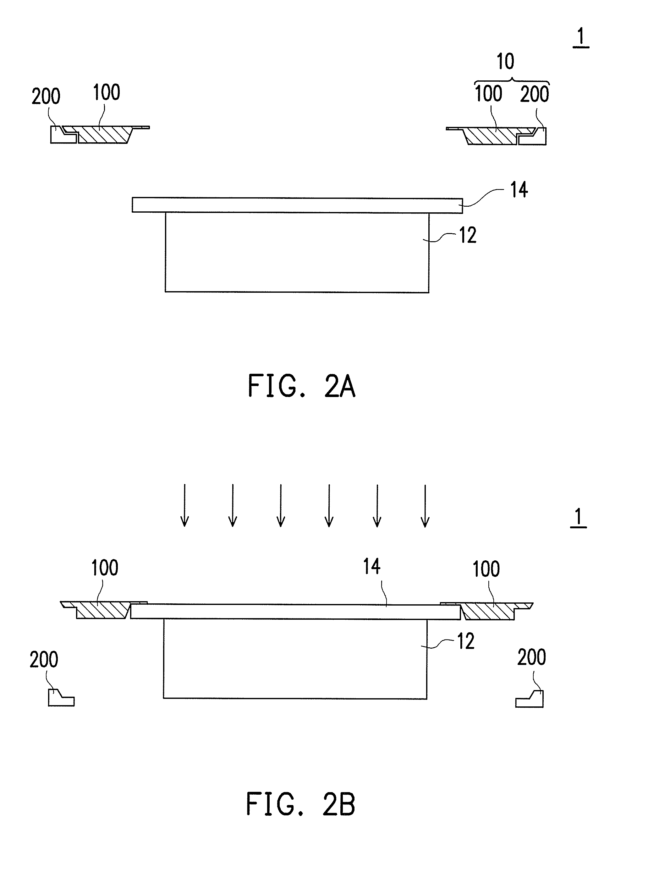
[0029]Referring to FIG. 1A and FIG. 1B, a workpiece clamp 10 includes an inner ring 100. The inner edge 100a of the inner ring 100 is divided into a circular arc portion 102 and two first line portions 104 and 106.

[0030]The first line portions 104 and 106 are connected to each other and located at the notch or opening of the circular arc portion 102. The circular arc portion 102 has a circle centre 103. The first line portions 104 and 106 are connected...


PUM


Abstract

A workpiece clamp including an inner ring is provided. The inner edge of the inner ring can be divided into a circular arc portion and two first line portions. The first line portions are connected to each other and located at the notch of the circular arc portion. The circular arc portion has a circle centre. The first line portions are connected at a connecting point. The included angle between the connecting line from the circle centre to the connecting point and each first line portion is greater than about 90 degrees and less than about 93 degrees.

Description

CROSS REFERENCE TO RELATED APPLICATION[0001]This application claims the priority benefit of Taiwan application serial no. 104116284, filed on May 21, 2015. The entirety of the above-mentioned patent application is hereby incorporated by reference herein and made a part of specification.BACKGROUND OF THE INVENTION[0002]1. Field of Invention[0003]The present invention is related to a semiconductor part, and more particularly to a workpiece clamp.[0004]2. Description of Related Art[0005]Thin film deposition has been one of the most widely applied techniques in the semiconductor industry. Thin film deposition can be divided into a physical vapour deposition (PVD) and a chemical vapour deposition (CVD). The former is carried out through a physical phenomenon, while the latter is carried out through a chemical reaction. No matter what kind of vapour deposition is carried out, a deposition machine is required for the related processes.[0006]The wafer is usually fixed by the wafer clamp on ...

Claims


Application Information

Patent Timeline
Patent Type & Authority Applications(United States)
IPC IPC(8): H01L21/687
CPCH01L21/68721
Inventor TIEN, CHI-HUNG
Owner EPISIL TECH INC
Why Eureka
Try Eureka