Rockshaft and frame in an agricultural implement

a technology of agricultural implements and frames, applied in the field of agricultural implements, can solve problems such as difficulty in distributing weight within the machine, movement of hitches, and inability to adjust, and achieve the effect of increasing machine stability

Active Publication Date: 2020-01-28
BLUE LEAF I P INC
View PDF25 Cites 0 Cited by
  • Summary
  • Abstract
  • Description
  • Claims
  • Application Information

AI Technical Summary

Benefits of technology

[0012]One advantage of the present invention is that the rockshaft is located in the middle of the frame elevation, thereby increasing machine stability over that achieved with the rockshaft located either above or below the frame.

Problems solved by technology

Either of the alternative mounting locations for the rockshaft can result in disadvantages or undesirable effects.
With a long pedestal arm, the pivot moves forward, and can create weight distribution difficulties within the machine.
On a constant level machine, inconsistent weight distribution can result in the hitch clevis moving up and down in the tractor drawbar.
On a floating hitch unit, the improper weight distribution can result in wheel wobble and can increase the tendency of the machine to tip.
With the rockshaft positioned below the frame, the structure is carried closer to the ground surface, which can lead to congestion for residue flow through the machine.

Method used


Image

  • Rockshaft and frame in an agricultural implement
  • Rockshaft and frame in an agricultural implement
  • Rockshaft and frame in an agricultural implement

Examples


Embodiment Construction

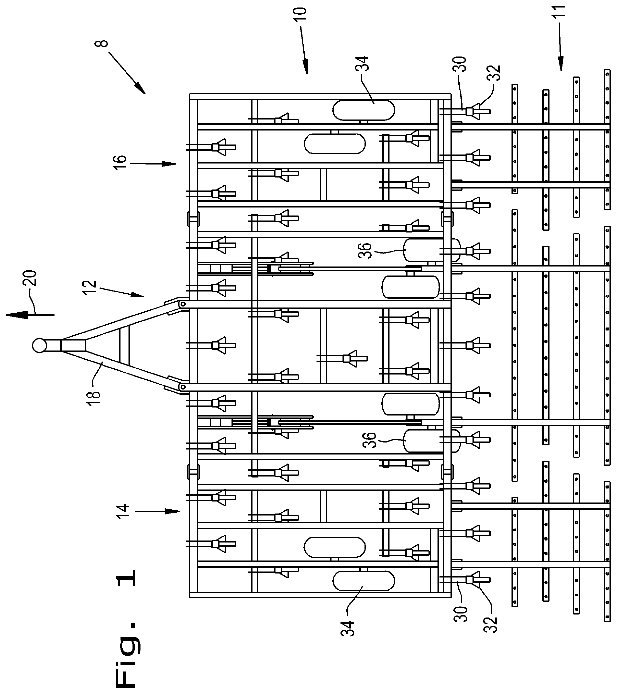
[0020]Referring now to the drawings, and more particularly to FIG. 1, there is shown a schematic illustration of an embodiment of an agricultural tillage implement 8, which can incorporate the rockshaft and frame disclosed herein. In the illustrated embodiment, the tillage implement 8 includes cultivator 10 and a harrow 11 for tilling soil prior to seeding. Field cultivator 10 is configured as a multi-section field cultivator, and includes a center frame section 12 and wing sections 14 and 16. Center frame section 12 is the center section that is towed directly by a traction unit, such as an agricultural tractor (not shown). A pull hitch 18 extends forward from center frame section 12 and is coupled with the traction unit in known manner so that the traction unit can tow implement 8 in a travel direction indicated by arrow 20.

[0021]Center frame section 12 and wing sections 14, 16 generally function to carry field working devices such as cultivator shanks 30 with shovels 32 at the lo...


PUM


Abstract

An agricultural implement has a main frame including fore-to-aft and cross frame members. Main lift and transport wheels are connected to rockshaft pedestal arms that are pivotally connected to the main frame by way of a rockshaft held by the main frame. The rockshaft is held spanning a distance between upper and lower fore-to-aft frame member components.

Description

BACKGROUND OF THE INVENTION1. Field of the Invention[0001]The present invention relates generally to agricultural implements, and, more particularly, to the frames, lift and depth control mechanisms for agricultural tillage implements.2. Description of the Related Art[0002]Farmers utilize a wide variety of tillage implements to prepare soil for planting. Some such implements include two or more sections coupled together to perform multiple functions as they are pulled through fields by a tractor. For example, a field cultivator is capable of tilling soil and leveling the tilled soil in a single pass during preparation for planting. A field cultivator has a frame that carries a number of cultivator shanks with shovels at their lower ends for tilling the soil. The field cultivator converts compacted soil into a level seedbed with a consistent depth for providing desired conditions for planting of a crop. Grass or residual crop material disposed on top of the soil is also worked into t...

Claims


Application Information

Patent Timeline
Patent Type & Authority Patents(United States)
IPC IPC(8): A01B63/22
CPCA01B63/22A01B19/02
Inventor SUDBRINK, MATTHEW R.KNOBLOCH, DEAN A.
Owner BLUE LEAF I P INC
Why Eureka
Try Eureka