Pneumatic Stirling expansion machine

An expander and pneumatic technology, applied in the field of expanders, can solve the problems of size and weight of Stirling refrigerators, high processing costs, and additional components, etc., to reduce the volume and weight of the whole machine, and improve reliability and stability , Easy installation and positioning effect

Pending Publication Date: 2021-02-05
南通智能感知研究院 +1
View PDF0 Cites 0 Cited by
  • Summary
  • Abstract
  • Description
  • Claims
  • Application Information

AI Technical Summary

Problems solved by technology

However, although the column spring has a simple structure and is easy to manufacture, it has a self-vibration phenomenon during axial operation, and due to the required stiffness requirements, it is necessary to increase the length and weight of the components and significantly increase the length of the machine. The increase in the size and weight of the Stirling refrigerator makes the Stirling refrigerator larger and heavier, thereby reducing its power-to-weight and power-to-volume ratio; the leaf spring has the characteristics of long life due to its structural form, but its structure is complicated and the processing cost is high. And the radial dimension is large, and there are also problems of large volume and mass

Method used


Image

  • Pneumatic Stirling expansion machine
  • Pneumatic Stirling expansion machine
  • Pneumatic Stirling expansion machine

Examples


Embodiment Construction

[0023] The following will clearly and completely describe the technical solutions in the embodiments of the present invention with reference to the accompanying drawings in the embodiments of the present invention. Obviously, the described embodiments are only some, not all, embodiments of the present invention. Based on the embodiments of the present invention, all other embodiments obtained by persons of ordinary skill in the art without making creative efforts belong to the protection scope of the present invention.

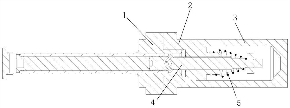
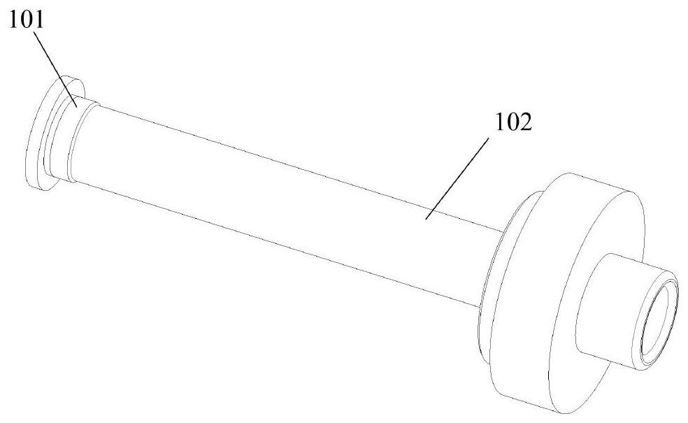
[0024] Such as Figure 1-6 As shown, this specific embodiment discloses a pneumatic Stirling expander, including a cold finger 1, a base 2, an end cover of the pneumatic chamber 3, a regenerator assembly 4 and a conical spring 5, and the base 2 is sleeved on the cold At one end of the finger 1, the pneumatic cavity end cover 3 is set on the base 2, the pneumatic cavity end cover 3 is located at the end far away from the cold finger 1, the regenerator assembly ...


PUM


Abstract

The invention discloses a pneumatic Stirling expansion machine which comprises a cold finger, a base, a pneumatic cavity end cover, a regenerator assembly and a conical spring. The base is arranged atone end of the cold finger in a sleeving manner, the pneumatic cavity end cover covers the base, the pneumatic cavity end cover is located at the end away from the cold finger, and the regenerator assembly penetrates through the cold finger and a center through hole of the base; and the regenerator assembly is fixed in the base, the conical spring is arranged at the front end of the regenerator assembly, the conical spring is connected to the front end of the base, the pneumatic cavity end cover covers the base, the conical spring and the front end of the regenerator assembly both cover the pneumatic cavity end cover, the conical spring is connected with the base through a spring seat, and the spring seat and the base are integrally formed. The pneumatic Stirling expansion machine has theadvantages that by using the conical spring, self-vibration caused by axial movement of the spring can be reduced in the operation process, the stability of the whole Stirling expansion machine is improved, meanwhile, the axial length of the spring is reduced, and the size and the weight of the whole Stirling expansion machine are reduced.

Description

technical field [0001] The invention relates to the field of expanders, in particular to a pneumatic Stirling expander. Background technique [0002] The expander is a machine that uses the principle of outputting mechanical work to reduce the temperature of the gas when the compressed gas expands and depressurizes to obtain cooling capacity. A typical pneumatic Stirling expander in the prior art requires a reciprocating member to provide reciprocating force during the working process of the expander. In the prior art, a typical column spring is usually used with a helical path uniformly arranged in the axial direction, and its two ends are connected to the main body that reciprocates along the central axis, which plays a role in supporting the movement of the main body; there are also plate springs, The leaf spring has a surrounding peripheral frame and an inwardly extending cantilever, which mainly relies on the cantilever to achieve the reciprocating movement of the body...

Claims


Application Information

Patent Timeline
Patent Type & Authority Applications(China)
IPC IPC(8): F25B9/14F28D20/00
CPCF25B9/14F28D20/00F28D2020/0017Y02E60/14
Inventor 朱海峰周伟楠蒋珍华汤逸豪陈雷吴亦农王仕越
Owner 南通智能感知研究院
Why Eureka
Try Eureka