Method for establishing a communication link between subscriber stations of a switching system which comprises two communication networks

a communication link and switching system technology, applied in the field of methods, can solve the problems of deterioration in quality during transmission, problem also occurring, and more serious, and achieve the effect of simple and reliable signaling procedure and alleviation of signal processing load

Inactive Publication Date: 2008-11-04
NOKIA SIEMENS NETWORKS GMBH & CO KG
View PDF18 Cites 5 Cited by
  • Summary
  • Abstract
  • Description
  • Claims
  • Application Information

AI Technical Summary

Benefits of technology

[0026]This has the advantage, on the one hand, that in the event of call forwarding to a subscriber station to be called the communication signals are subject to the same number of conversion processes between the first communication network and the second communication network, as in the case of a regular connection between two sub-scriber stations, and on the other hand, that a relatively simple and reliable signaling procedure can be used to establish the communication connection between the calling subscriber station and the subscriber station to be called. Existing standard devices, which are deployed for setting up communication connections in the respective switching network, can be used for this signaling procedure in the individual switching networks.
[0027]The signaling connection between the switching center to which the calling subscriber station is linked, and the switching center at which the subscriber station to be called was hitherto available, is expediently set up via control devices, which on the one hand, are connected to the relevant switching centers and the transition devices connected to these and, which on the other hand, are connected to each other. This advantageously allows signaling connections between calling subscriber stations and subscriber stations to be called to be established in a particularly flexible manner within the overall switching system. Existing standard devices, which are deployed for setting up communication connections in the respective switching network, can thereby be used in the individual switching networks.
[0028]The respective signaling connection between the respective calling subscriber station and the subscriber station to be called in each instance is expediently processed in a corresponding manner to the respective communication connection between the relevant subscriber stations. This has the advantage that, after identification of a call redirection situation in respect of the sub-scriber station to be called, a signaling connection no longer has to be routed via the switching center of the first communication network at which the subscriber station to be called was hitherto available, thereby alleviating the signaling processing load.
[0029]The control or signaling information stored in the control devices of the transition devices involved in the respective connection is preferably deleted after termination of the communication connection between the sub-scriber stations connected to each other in each instance. This ensures that no unnecessary information or data remains in the control devices after termination of the respective communication connection.

Problems solved by technology

In addition to the problem highlighted above, a further, in some cases more serious, problem also occurs in the event of call forwarding or call redirection in respect of a subscriber station to be called.
However this is associated with marked delay times and therefore also a deterioration in quality during transmission of the respective communication signals between the calling subscriber station and the subscriber station to be called.
These delay times result primarily from packet assembly and disassembly processes due to the transitions between the switching networks.

Method used


Image

  • Method for establishing a communication link between subscriber stations of a switching system which comprises two communication networks
  • Method for establishing a communication link between subscriber stations of a switching system which comprises two communication networks

Examples


Embodiment Construction

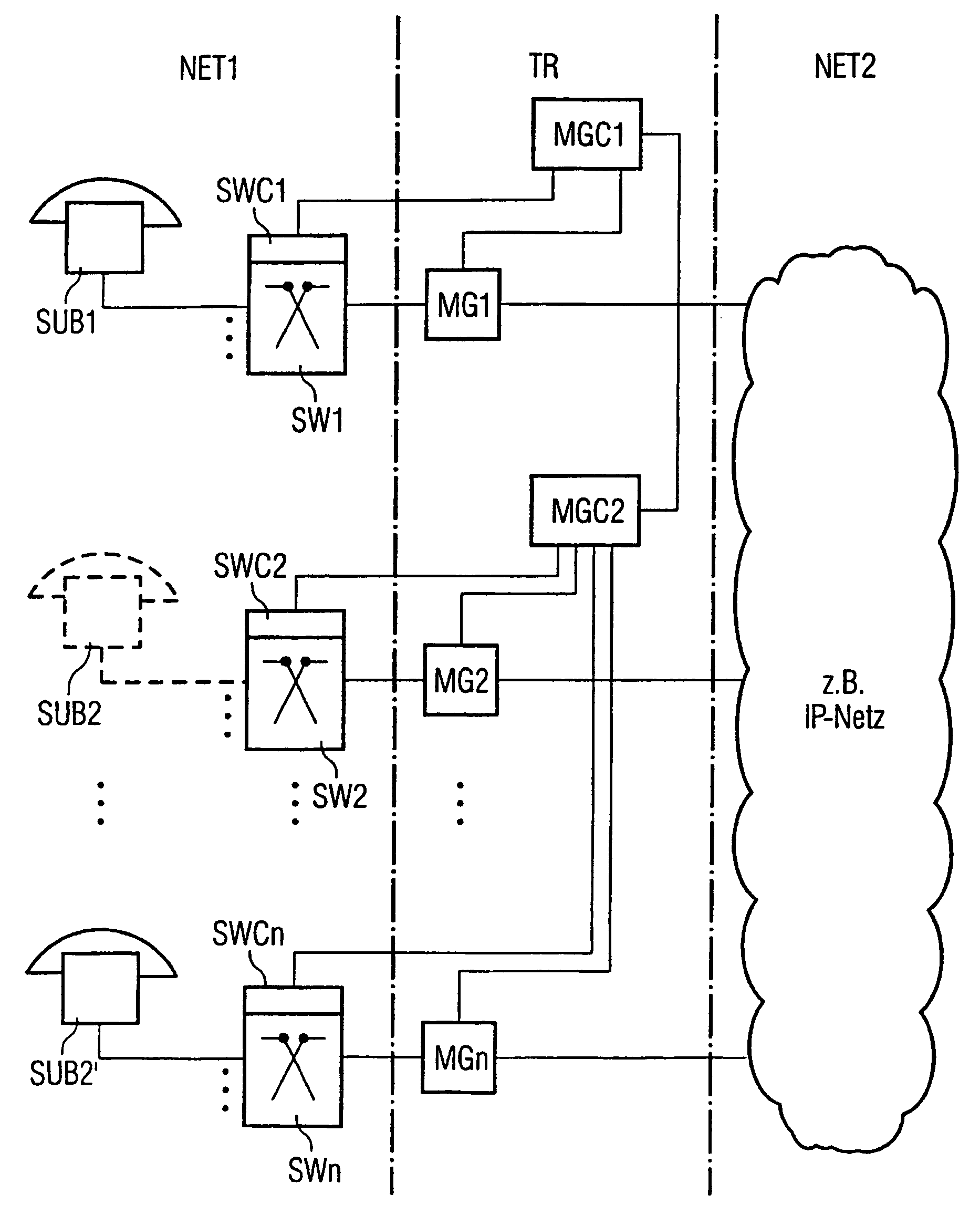
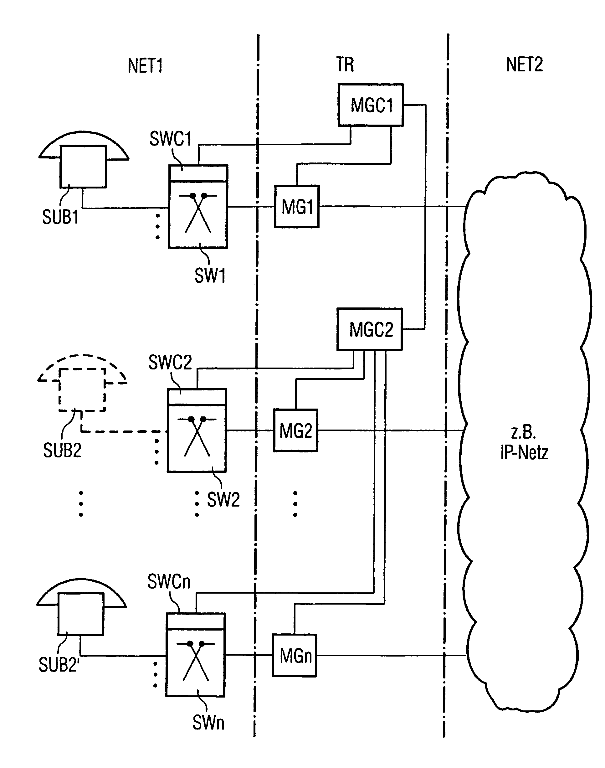
[0032]Associated with the switching system shown in the drawing is a first communication system NET1, which may for example be a time-multiplex switching system, such as the EWSD system in commercial use. This first communication network NET1 has a plurality of switching centers SW1, SW2 to SWn, which are equipped with their own control devices SWC1, SWC2 to SWCn (only shown diagrammatically here). These control devices SWC1 to SWCn are used both to select the respective switching center as a function of control and / or signaling information, in particular dialing information, from subscriber stations which are linked to the respective switching center, and to receive and forward such control and / or signaling information from or to the transition area TR shown in the drawing.

[0033]Linked to the switching centers SW1 to SWn of the first communication network NET1 is a plurality of subscriber stations, which may include telephone subscriber terminals, fax machines, data terminals, PCs ...


PUM


Abstract

In a switching system, the subscriber stations of which are linked to a switching centers of a first communication network, which are connected to each other through a second communication network, such as the internet, by means of transition devices, with which separate control devices are associated to control the connection traffic as a function of control and/or signaling information. A communication connection is established to a subscriber station to be called, the availability of which has changed from one switching center to another switching center, by first setting up a signaling connection to the switching center at which the subscriber station to be called was hitherto available, whereupon a communication connection is established using the control and/or signaling information specifying the changed availability of the subscriber station to be called directly to the other switching center at which the subscriber station to be called is now available, via the transition device connecting this switching center to the second communication network.

Description

CLAIM FOR PRIORITY[0001]This application claims priority to International Application No. PCT / EP02 / 11018, which was published in the German language on Apr. 24, 2003, which claims the benefit of priority to European Application No. 01124526.3 which was filed in the German language on Oct. 12, 2001.TECHNICAL FIELD OF THE INVENTION[0002]The invention relates to a method for establishing a communication connection between calling subscriber stations and subscriber stations to be called.BACKGROUND OF THE INVENTION[0003]An IP network here refers to a switching and transmission network, in which communication signals are switched or transmitted on the basis of an internet protocol.[0004]Switching network configurations of the type mentioned above will in future supplement or even supersede conventional communication networks, such as time-multiplex switching networks. In the transition devices between the switching centers of the first communication network and the second communication ne...

Claims


Application Information

Patent Timeline
Patent Type & Authority Patents(United States)
IPC IPC(8): H04L12/28H04M3/54H04M7/00
CPCH04M3/54H04M7/0072H04M7/1245H04M7/1285
Inventor KNAEBCHEN, ANDREAS
Owner NOKIA SIEMENS NETWORKS GMBH & CO KG
Why Eureka
Try Eureka