
Shear wall template

a template and masonry technology, applied in the field of masonry member anchoring, can solve the problem of not being able to fit the selected structural element to be anchored over all the bolts, and achieve the effect of strengthening the template, preserving material, and being more rigid

Active Publication Date: 2008-11-04
SIMSON STRONG TIE COMPANY
View PDF72 Cites 46 Cited by
  • Summary
  • Abstract
  • Description
  • Claims
  • Application Information

AI Technical Summary

Benefits of technology

The template provides accurate, durable, and reusable positioning of multiple anchor bolts, maintaining their alignment and spacing, and is adaptable to different form configurations, ensuring proper embedding and easy removal, thus enhancing construction efficiency and accuracy.

Problems solved by technology

If one of the bolts is skewed with respect to the others, even if protrudes from the foundation at the proper location, it may not be possible to fit the selected structural element to be anchored over all the bolts.

Method used


Image

  • Shear wall template
  • Shear wall template
  • Shear wall template

Examples


Embodiment Construction

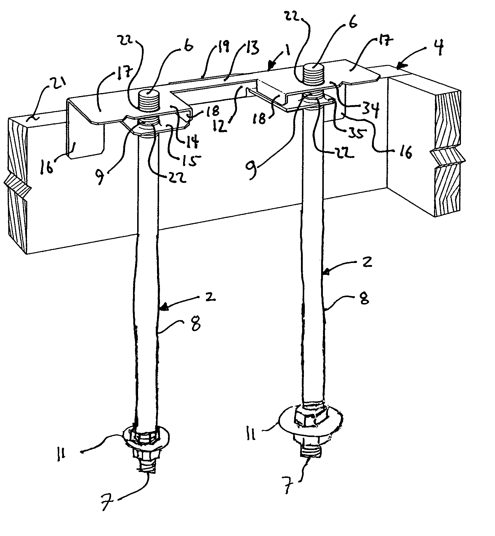
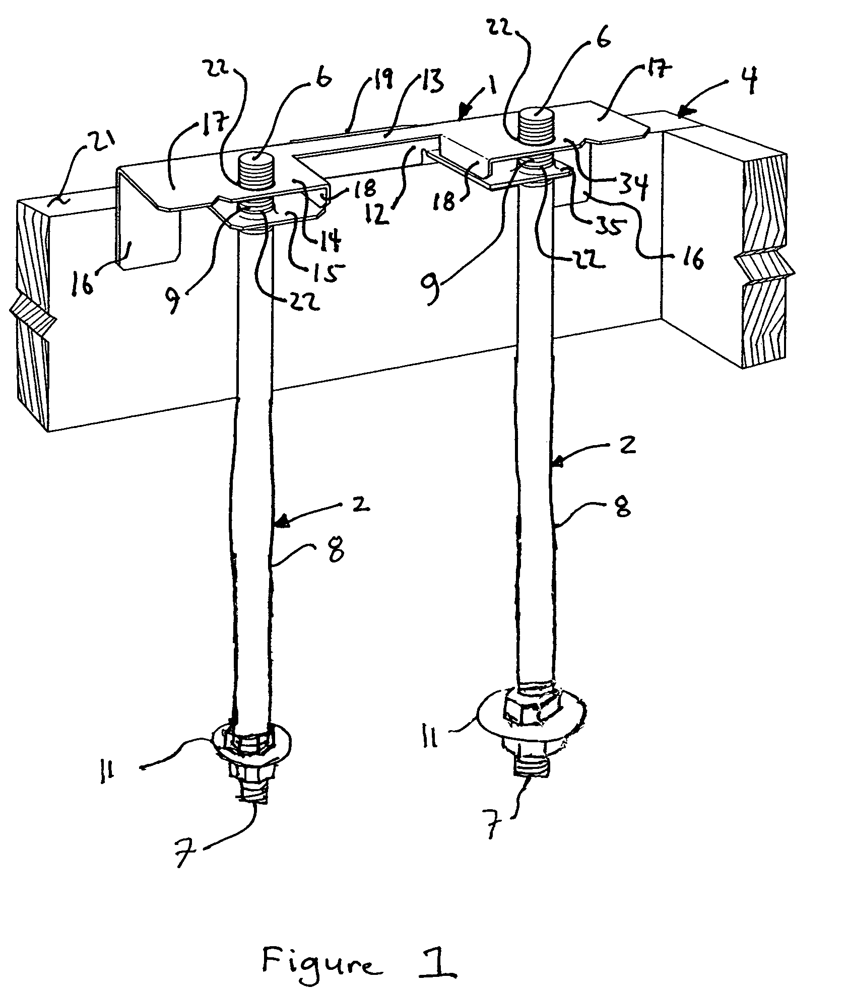
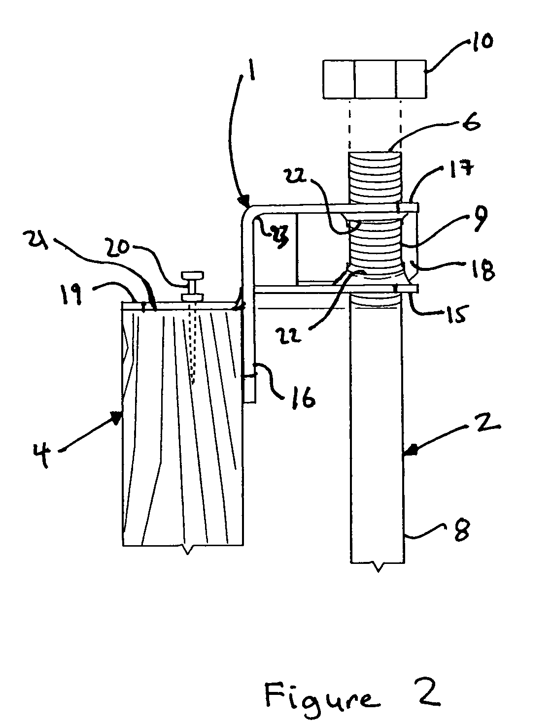
[0067]The present invention provide a template 1 for receiving and supporting a plurality of anchor bolts 2 that are to be partially embedded within a cementious member 3. The template 1 is used where the wet cement is to be poured around the anchor bolts 2 that are held in place. As shown in FIG. 1, the template can be attached to the form 4 that defines the edge of the concrete member 3, or, as is shown in FIG. 3, the template can be attached to a support 5 separate from the form 4.

[0068]As shown in FIG. 1, the anchor bolt 2 is provided with an upper end 6, a lower end 7 and a shank 8. The upper end 6 of the anchor bolt 2 is received by the template 1 with the upper end 6 of the anchor bolt 2 protruding through and above the template 1. In the preferred embodiment, the upper end 6 of the anchor bolt 2 and the upper portion of the shank 8 of the anchor bolt 2 is provided with a threaded portion 9 to receive a standard nut 10, which is shown in FIGS. 2 and 37. In the preferred embod...


PUM

PropertyMeasurementUnit
distanceaaaaaaaaaa
angleaaaaaaaaaa
angleaaaaaaaaaa

Abstract

A connection is provided between a holder and a plurality of anchor bolts by means of a template. The holder is typically a form board for a cementious member such as a foundation. The template is releasably attached to the form board. The template is formed with a central elongated support, and a plurality of pairs of primary and secondary anchor bolt receiving platforms connected to the central elongated support. The pairs of primary and second anchor bolt receiving platforms are spaced along the central elongated support from each other. Each of the primary and secondary anchor bolt receiving platforms has an opening therein for receiving one of the anchor bolts there through, the openings in each pair of primary and secondary anchor bolt receiving platforms being in alignment so as to receive the same one of the anchor bolts. A plurality of fasteners are releasably connected to the plurality of anchor bolts and are supported by the template to releasably attach the anchor bolts to the template, suspending them in the form where wet cement can surround and envelope the lower portions of the anchor bolts.

Description

BACKGROUND OF THE INVENTION[0001]The present invention relates to setting anchors in a masonry member, and more specifically to suspending a plurality of anchor bolts from a template and then pouring a wet concrete foundation around the anchor bolts that will then set with the anchor bolts embedded and protruding from it.[0002]It is a generally accepted practice in most parts of the United States to anchor the exterior walls of light frame buildings to the foundation with anchor or bolts that are partially embedded in the foundation and protrude form the top surface of the foundation of the building. It is also becoming more common to see interior walls similarly anchored to the foundation.[0003]One common method of forming a concrete foundation with anchor bolts protruding from its top surface at selected locations is to suspend the anchor bolts in the space defined by the foundation's form and then pour the wet concrete around the anchor bolts. Sometimes the bolts can be supported...

Claims


Application Information

Patent Timeline
Patent Type & Authority Patents(United States)
IPC IPC(8): E04G17/12E04B1/41E04C5/00E04G21/18
CPCE04B1/4157E04G21/185
Inventor GRIDLEY, JERRY G.LIN, JIN-JIE
Owner SIMSON STRONG TIE COMPANY
Learn More