
Scanning imaging apparatus

a scanning apparatus and scanning technology, applied in the direction of direction finders, instruments, measurement devices, etc., can solve the problem of physical size of the scanning apparatus working at millimetre wavebands or thereabouts, and achieve the effect of limited power requirements and good off-axis performan

Active Publication Date: 2008-10-28
QINETIQ LTD
View PDF9 Cites 2 Cited by
  • Summary
  • Abstract
  • Description
  • Claims
  • Application Information

AI Technical Summary

Benefits of technology

[0016]It is an object of the present invention to provide a compact object space scanning apparatus which may be used, in particular, to implement real-time imaging at millimetre wavebands or thereabouts, or in radar systems. It is also an object of the invention to provide a scanning apparatus which has limited power requirements, no out-of-balance forces and gives good off axis performance.
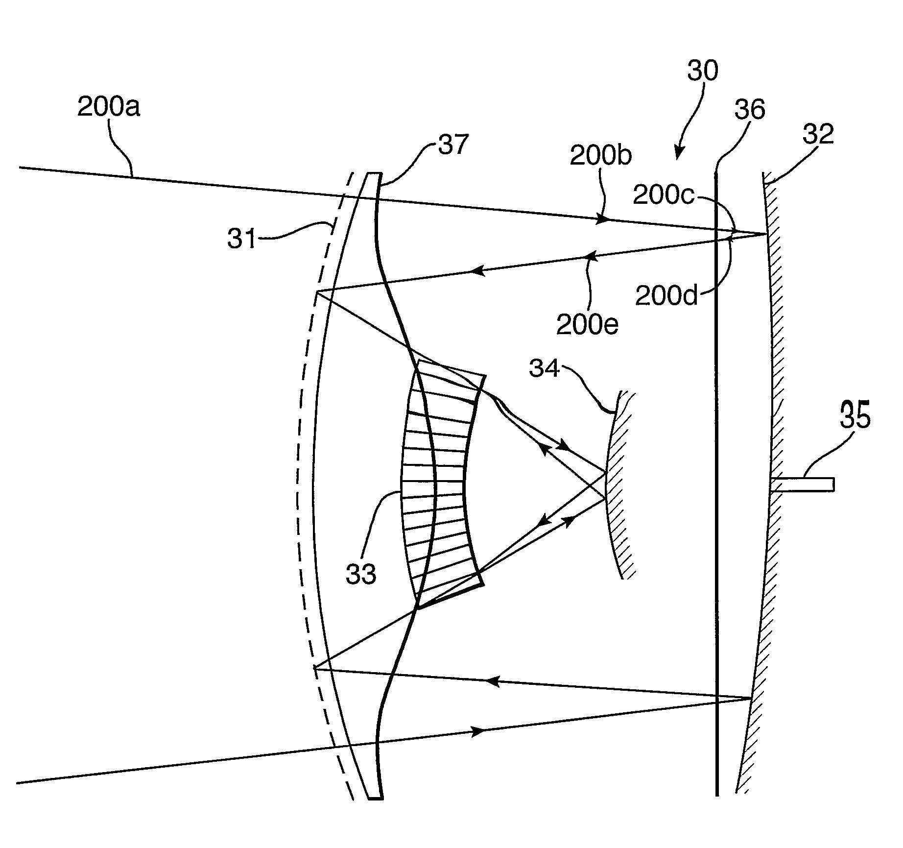
[0021]characterised in that the optical system further includes a convex sub-reflector that acts in combination with the curved polariser / reflector to bring radiation to a focus at an image plan e, the sub-reflector providing an increased system focal length.
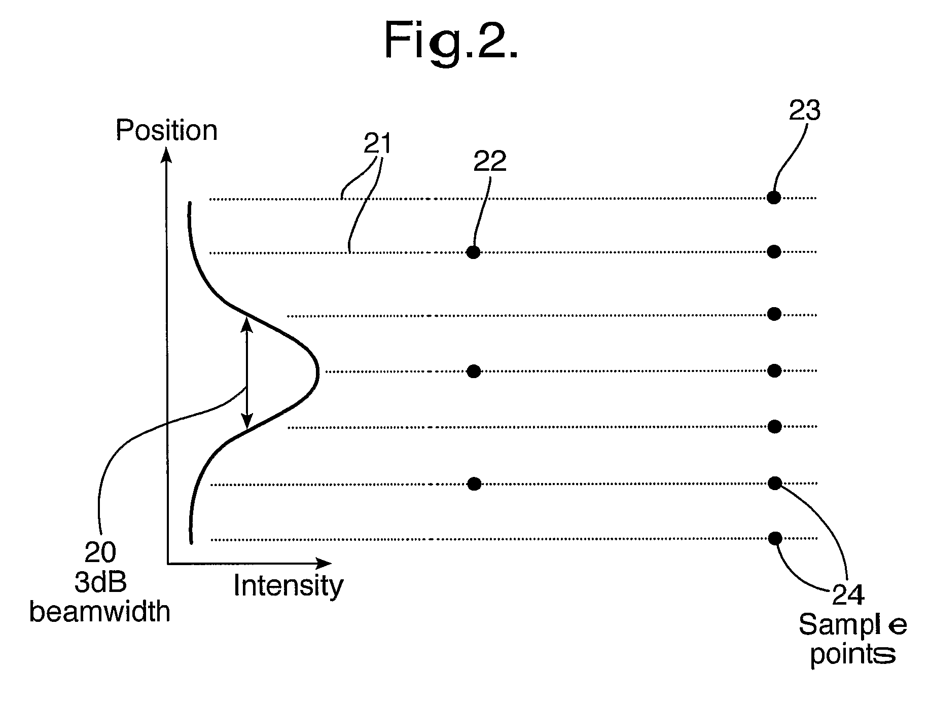
[0023]However, it has been found that increasing the focal length has significant advantages over the prior art imager. The use of a longer focal length increases the permissible spacing of the receiver elements' antennas on the image plane whilst still maintaining sufficient spatial sampling of the image plane to ensure continuous coverage of a scene to be imaged.
[0024]The invention employs a convex sub-reflector in the optical path of the radiation that provides the increased focal length. This effectively converts the optical system of the prior art WO2002 / 066998 from a modified Schmidt system to a modified Schmidt-Cassegrain system. This has a further benefit over the prior art in that the image p lane may have a curvature in the opposite manner to that of the prior art. Indeed, in some embodiments the system image plane is concave in profile. The divergent nature of normals projected from the concave image plane to a region behind it thus means that there will be more space behind each antenna element sitting on the image plane to accommodate the electronics associated with each antenna.
[0025]The convex sub-reflector focussing element may preferably be arranged to be moveable with respect to the other focussing elements, so allowing a convenient means for changing the focus of the system. This allows a significant advantage over the prior art, where to focus the system requires the whole of the receiver array to be moved, leading to complications with mounting and cabling.

Problems solved by technology

The physical size of imagers working at millimetre wavebands or thereabouts is currently an issue amongst users of such systems.

Method used


Image

  • Scanning imaging apparatus
  • Scanning imaging apparatus
  • Scanning imaging apparatus

Examples


Embodiment Construction

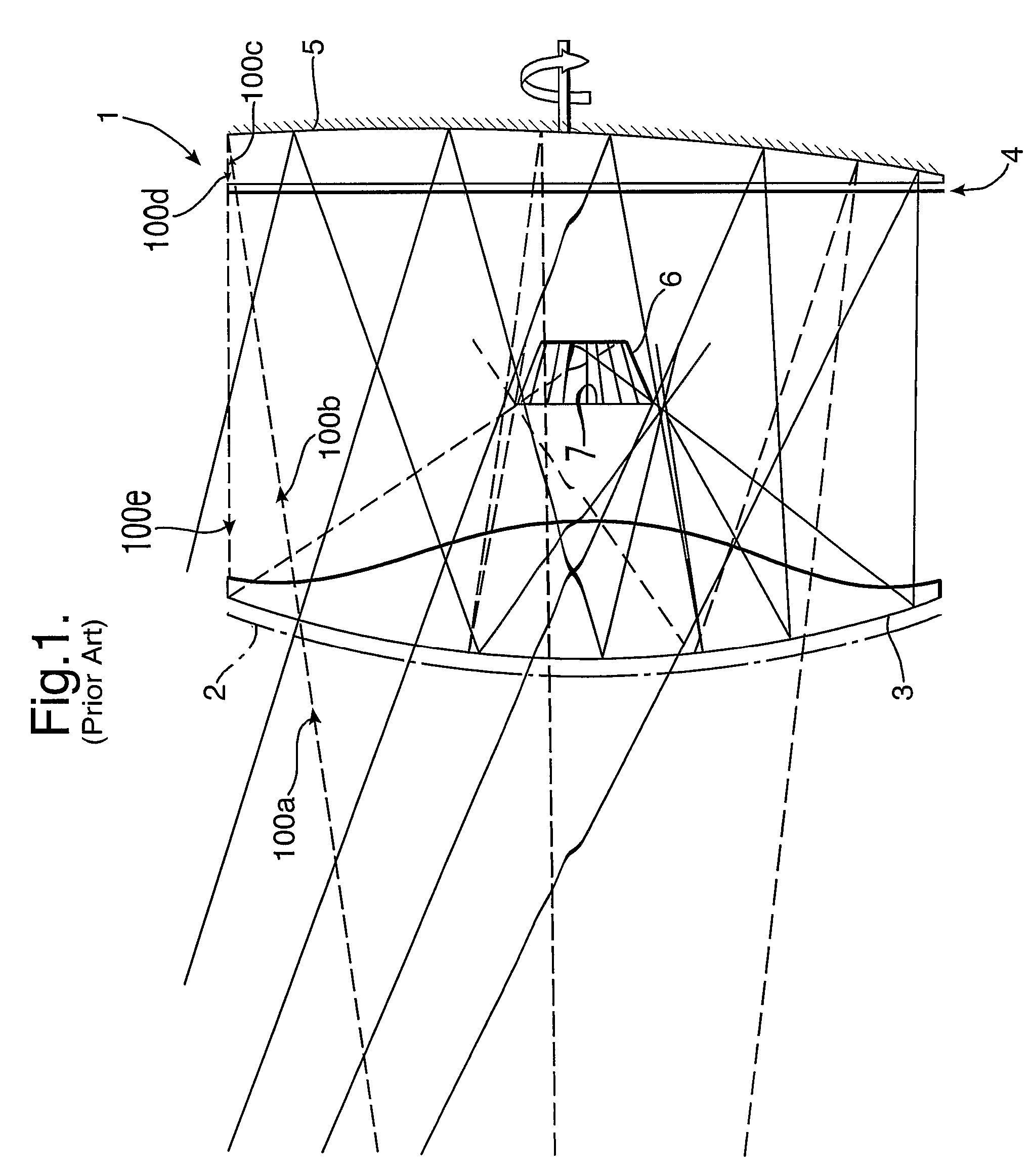
[0032]Shown in FIG. 1 is a scanning imager of the prior art, of the type described in Applicant's co-pending patent application PCT / 2004 / 002520. This shows an imager 1 incorporating a curved polariser / reflector 2 which allows radiation 100a of a specific polarisation 100b to pass therethrough whilst reflecting radiation of orthogonal polarisation. This curved polariser / reflector 2 may also contain a dielectric material 3 acting as both a physical support and a lens that may be used to help correct system aberrations.

[0033]The next component in the optical path is a quarter-wave plate 4, followed by a curved rotatable reflector 5. Linearly polarised radiation 100b passes through the quarter wave plate 4 and hence becomes circularly polarised 100c. It then gets reflected from the rotatable reflector 5, where the polarisation changes handedness 100d, and passes again through the quarter-wave plate 4 which converts the radiation to linearly polarised radiation 100e of an orthogonal dire...


PUM


Abstract

A scanning imaging apparatus comprises an optical system including a curved polariser / reflector, a rotatable reflector, a polarisation twisting plate, and a receiver array, wherein a convex reflective element is incorporated in the optical path that acts as a sub-reflector that increases the optical system focal length. It has been found that an increase to the optical focal length in this manner gives a greater 3 dB spot size at the image plane, thus easing design constraints on the receiver array packing density, whilst maintaining a given spatial sampling interval. An additional benefit is that radiation from differing scan locations diverges as it approaches the image plane, which provides more volume in which to position receiver electronics. Focussing of the optical system may be achieved by movement of the sub-reflector.

Description

[0001]This application is the U.S. national phase of international application PCT / GB2005 / 003942 filed 14 Oct. 2005, which designated the U.S. and claims benefit of GB 0423595.8 filed 23 Oct. 2004, the entire contents of each of which are hereby incorporated by reference.BACKGROUND OF THE INVENTION[0002]1. Field of the Invention[0003]This invention relates to scanning apparatus which may be used in a real-time imaging system, and has particular utility in a real-time passive millimetre wave imaging system, as well as at other wavelengths. The scanning imaging apparatus may also be used in other radiometry systems.[0004]2. Description of Prior Art[0005]Imaging using electromagnetic radiation at millimetre wavelengths, or thereabouts, is potentially useful as an all-weather surveillance and guidance aid and for indoor and outdoor security applications, but any practically useful system must be capable of imaging in real-time. This was until recently a problem due to the high number of...

Claims


Application Information

Patent Timeline
Patent Type & Authority Patents(United States)
IPC IPC(8): G02B26/08G01S3/781G01S5/16
CPCG01S3/781G01S5/16
Inventor ANDERTON, RUPERT NCOWARD, PETER R
Owner QINETIQ LTD
Learn More