
Electrical drive system for a vehicle with skid steering

Inactive Publication Date: 2008-10-28
ZF FRIEDRICHSHAFEN AG
View PDF17 Cites 45 Cited by
  • Summary
  • Abstract
  • Description
  • Claims
  • Application Information

AI Technical Summary

Benefits of technology

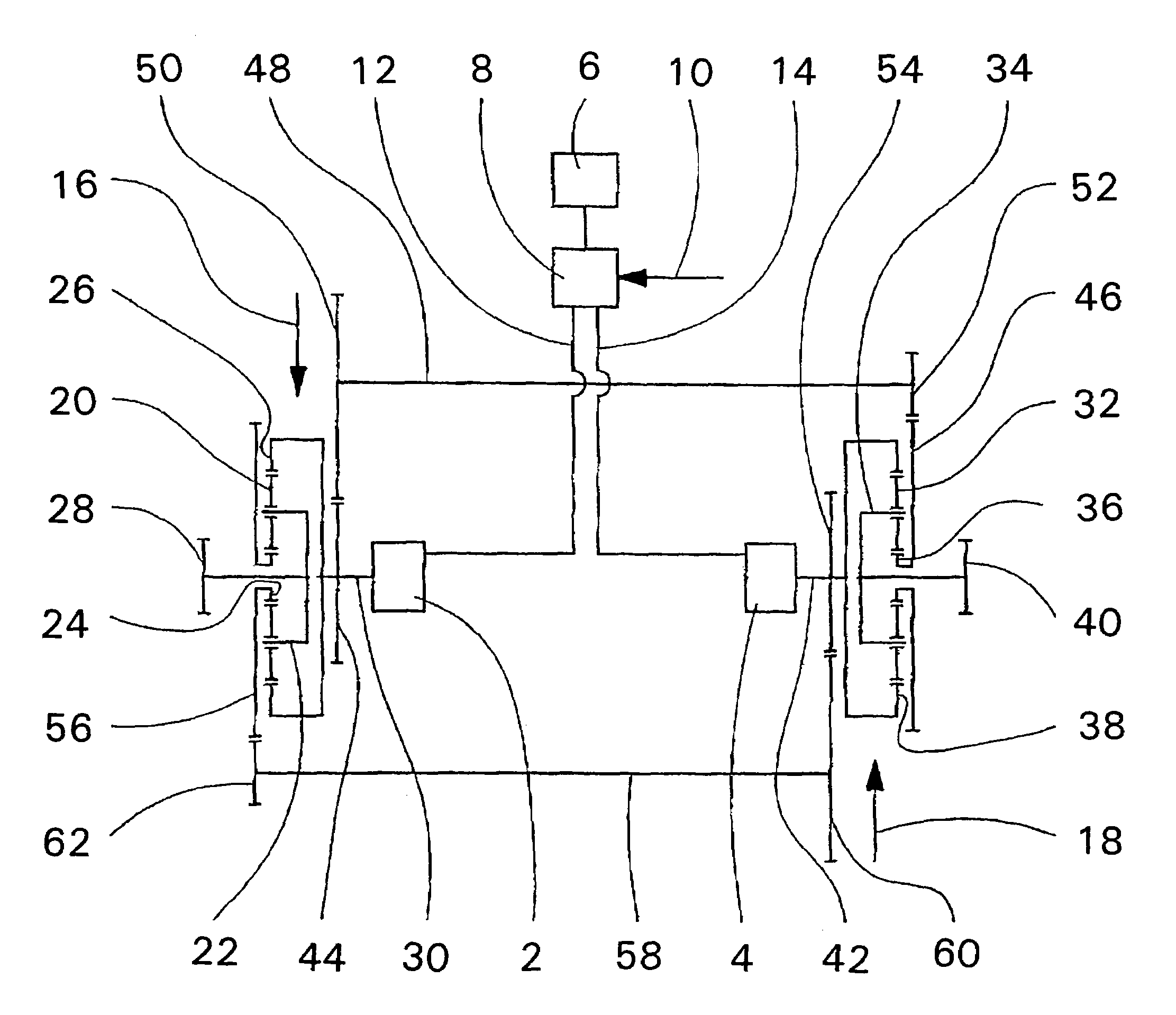
[0014]In a favorable arrangement, the invention requires that the first mechanical, torque-proof, gear train with the internal gear of the left gear unit be connected to the first spur gear, with the torque-proof sun gear of the right gear unit connected to the second spur gear and a connecting shaft, which exhibit a third and a fourth spur gear at their ends, whereby the third with first and the fourth with the second spur gear stand in interference. Accordingly, the second mechanical gear train is built torque-proof with an internal gear of the right gear unit connected to the fifth spur gear with a torque-proof, sun gear of the left gear unit connected to the sixth spur gear and a second connecting shaft, which exhibit a seventh and an eighth spur gear at their ends, whereby the seventh with the fifth and the eighth with the sixth spur gear stand in interference. For better utilization of energy, an electrical middle enclosure can be placed between the left and the right electrical drive engines, which at least in certain operating conditions, an electrical performance leads from the left drive engine working as a generator to the right drive engine working as engine and in reverse.

Problems solved by technology

In particular, with heavy tracked vehicles, this requires substantial brake performances on the inner drive chain.
This well-known drive system is, however, very complex and not optimal as far as space constrictions are concerned.

Method used


Image

  • Electrical drive system for a vehicle with skid steering
  • Electrical drive system for a vehicle with skid steering

Examples


Embodiment Construction

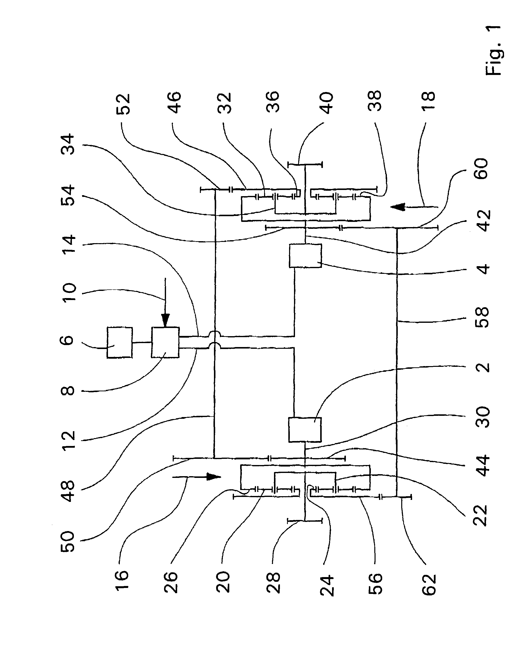
[0018]The invention is described on the basis of the enclosed design, which schematically shows an electrical drive system, according to the invention, for a vehicle with a skid steering element. In it, the left electrical, drive engine is marked with 2 and a right electrical drive engine with 4. An electrical energy source 6 can consist of a combination of a diesel engine with an electrical generator or also of a battery or a gas cell. An electronic control unit 8 covers control hard- and software as well as power electronics. Depending on a control input signal 10, which the driver produces by manipulation of unrepresented controls, into the two electric drives 2, 4 over lines 12, 14, depending on the control input signals 10, the appropriate number of revolutions are performed. A left gear unit 16 exhibits several planetary gears 20, which are stored on a swiveling planet, pinion cage 22. The planetary gears 20 are in synchronous operation with a sun gear 24 and an internal gear ...


PUM


Abstract

An electrical drive system for a vehicle with a skid steering element exhibits a homogeneous electrical drive engine and a homogeneous gear unit (16, 18) on the left and on the right side in each case, which are propelled by a drive engine (2,4), assigned in each case, and over a power drive flange (28, 40) to propel a track or a drive wheel. Two transfer elements (26, 24) of the left gear unit (16), which do not form the drive, are directly connected by a mechanical gear train crosswise in each case with both transfer elements (36, 38) of the right gear unit, which do not form the drive.

Description

[0001]This application is a national stage completion of PCT / EP2004 / 009614 filed Aug. 28, 2004 which claims priority from German Application Serial No. 103 44 711.3 filed Sep. 26, 2003.FIELD OF THE INVENTION[0002]The invention concerns an electrical drive system for a vehicle with a skid steering element.BACKGROUND OF THE INVENTION[0003]Vehicles with a skid steering element are tracked vehicles or wheeled vehicles in which, while driving along curves, the inner drive chain and / or the inner drive wheels are slowed down in each case opposite the outer drive chain and / or the outer drive wheels. In particular, with heavy tracked vehicles, this requires substantial brake performances on the inner drive chain.[0004]There are well-known different systems, which permit this brake performance being supplied to the outer drive chain. With a mechanical or hydrostatic-mechanical, superimposed, steering gear with a steering gear part and a driving transmission part, as is revealed in DE 38 33 78...

Claims


Application Information

Patent Timeline
IPC IPC(8): B60K1/00B62D11/04
CPCB62D11/04B62D11/02B62D11/00
Inventor SORG, JOHANNES
Owner ZF FRIEDRICHSHAFEN AG
Learn More