
Constant vertical state maintaining cueing system

a cueing system and constant vertical state technology, applied in process and machine control, instruments, navigation instruments, etc., can solve the problems of limiting the ability to maintain the desired vertical state, the inceptor positions required to maintain the vertical state exceed one or more of the vertical axis limits, and the inability to maintain the vertical state or the limit,

Inactive Publication Date: 2008-10-21
THE BOEING CO
View PDF43 Cites 30 Cited by
  • Summary
  • Abstract
  • Description
  • Claims
  • Application Information

AI Technical Summary

Benefits of technology

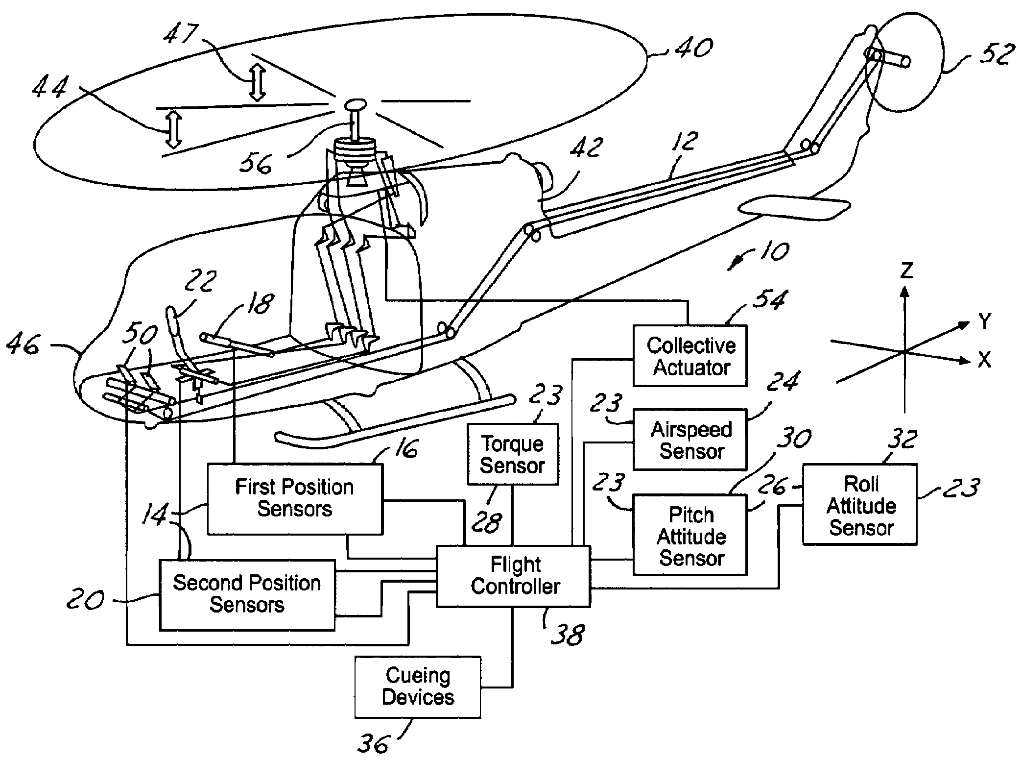
[0023]Another advantage of the present invention is that it relies only on parameters readily available in most aeronautical vehicles, such as helicopters. The minimum data that is required from aircraft sensors is torque, rotor speed, vertical velocity, pitch attitude and roll attitude. Other data that is available includes airspeed, and rate of change of altitude.
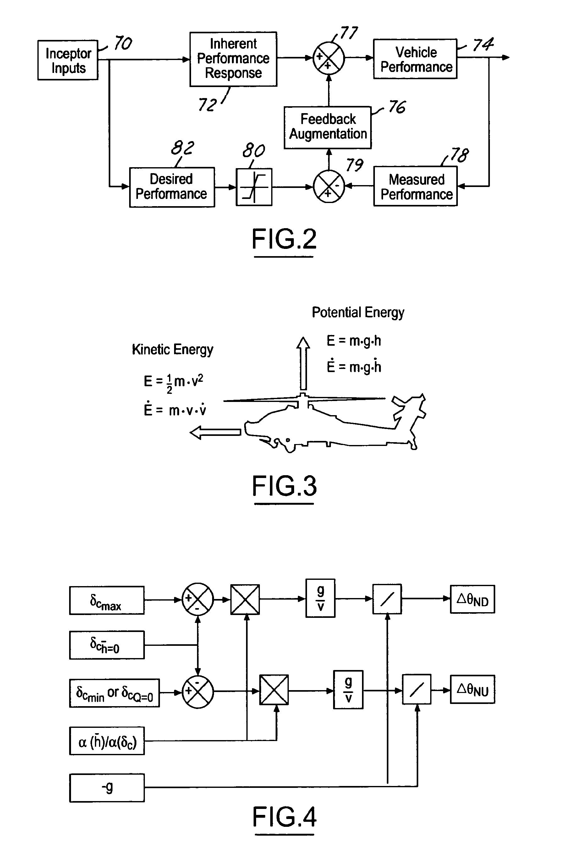
[0024]The vehicle controller determines a vertical inceptor position to maintain a vertical state. The controller positions the vertical inceptor or generates a signal to be summed in series with the vertical inceptor position or a combination of both to maintain the constant vertical state in response to the vehicle performance and operator inputs. The controller also determines the maximum and minimum vertical inceptor positions based on the vehicle limits. The allowable increase and decrease in the vertical inceptor before exceeding the maximum or minimum vertical inceptor positions is determined by the vehicle controller.
[0025]Using the principals of potential and kinetic energy, the allowable increase and decrease in the vertical inceptor position are related to the potential acceleration and deceleration on the longitudinal and lateral axes. An alternative method uses the relationship between the thrust required to maintain the vertical state and the gravitational force to relate the allowable increase and decrease in the vertical inceptor position to the maximum pitch or roll attitude of the vehicle.
[0026]The longitudinal and lateral acceleration and deceleration are directly related to the pitch and roll attitudes of the vehicle. Therefore the longitudinal and lateral acceleration and deceleration limits can be cued to the pilot as pitch and roll attitude limits. The pitch and roll attitude limits can be cued to the pilot through various methods including but not limited to tactile cues, aural cues, visual cues, and stick shakers. The pitch and roll limits can also be enforced by the vehicle controller without pilot intervention.

Problems solved by technology

Although vertical inceptor positions required to maintain a desired vertical state may currently be determined, since the vertical inceptor positioning effects power output of the engine as well as the collective pitch of the main rotor blades, there are many mechanical and aerodynamic limits associated with vertical inceptor positioning, which can limit the ability to maintain the desired vertical state.
Difficulties arise when, as a result of other vehicle operator actions such as commanding longitudinal and lateral accelerations, the vertical inceptor positions required to maintain the vertical state exceed one or more of the vertical axis limits.
Depending on methods used in maintaining the desired vertical state and the methods used in limiting vertical inceptor positioning, the exceedance of a vertical axis limit may result in disengagement from or inability to maintain the vertical state or exceedance of the limit(s).
Also, in order to be able to monitor instrumentation while navigating the vehicle, extensive training is required, which costs time and money.
Also, the vehicle operator to maintain the desired vertical state and not exceed a limit, typically, operates the vehicle in a conservative manner and does not utilize full performance capabilities of the vehicle.
A related problem for vehicle operators occurs if the desired vertical state changes and the airspeed must be reduced to enable the vehicle to maintain the new state.
It is sometimes necessary for the vehicle operator to require sudden deceleration or acceleration of the vehicle due to, for example, dangerous or hazardous situations.
However, it is often difficult for the operator to do so due to distractions and other concerns.
Altering vehicle response characteristic can result in time consuming and costly testing of a vehicle and re-training of vehicle operators.

Method used


Image

  • Constant vertical state maintaining cueing system
  • Constant vertical state maintaining cueing system
  • Constant vertical state maintaining cueing system

Examples


Embodiment Construction

[0039]While the present invention is described with respect to a method and system for cueing a helicopter vehicle operator as to maximum allowable accelerations and decelerations that may be performed during a constant vertical state without disengagement therefrom, the present invention may be adapted for any type of aeronautical vehicle or system.

[0040]In the following description, various operating parameters and components are described for one constructed embodiment. These specific parameters and components are included as examples and are not meant to be limiting.

[0041]Referring now to FIG. 1, a perspective and block diagrammatic view of a constant vertical state maintaining system 10 for helicopter-type aeronautical vehicle 12 in accordance with an embodiment of the present invention is shown. The cueing system 10 includes control inceptors 18 and 22 which are coupled to the flight controller 38 of the aeronautical vehicle. In the embodiment shown, the system 10 includes a v...


PUM


Abstract

This invention relates to the concept of managing the rate of change of energy in a helicopter or other aeronautical vehicle. The invention uses energy management calculations to determine the maximum longitudinal and lateral inputs that can be made while still enabling the vehicle to maintain a desired vertical state. The results of the calculations can be cued to the pilot either tactilely, aurally, or visually, or used for internal software limiting.

Description

RELATED APPLICATIONS[0001]This application is a divisional application of, and claims priority from, pending prior application Ser. No. 10 / 613,253, filed Jul. 3, 2003.GOVERNMENT CONTRACT[0002]This invention was made with Government support under contract DAAH10-00-C-0052 awarded by the United States Army. The Government has certain rights in this invention.TECHNICAL FIELD[0003]The present invention relates generally to aeronautical vehicle systems, and more particularly, to a method and system for cueing a vehicle operator as to maximum allowable accelerations and decelerations that may be performed while maintaining a constant vertical state without disengagement therefrom.BACKGROUND OF THE INVENTION[0004]In an aeronautical vehicle, such as a helicopter, a vehicle operator uses control inceptors to control the vehicle. Position changes of each control inceptor causes changes in orientation of aerodynamic surfaces and engine generated output power of the vehicle. In a helicopter suc...

Claims


Application Information

Patent Timeline
Patent Type & Authority Patents(United States)
IPC IPC(8): G06F17/00G05D1/08
CPCG05D1/0858
Inventor EINTHOVEN, PIETER G.MORSE, CHANNING S.
Owner THE BOEING CO
Learn More