
Communication network switching system and method thereof

a technology of communication network and switching system, which is applied in the direction of wireless communication, wireless communication, wireless commuication services, etc., can solve the problem of higher user charge for long-range wireless network system, and achieve the effect of reducing user charge fee and reducing frequency of us

Active Publication Date: 2008-10-21
MICROCHIP TECH INC +1
View PDF2 Cites 8 Cited by
  • Summary
  • Abstract
  • Description
  • Claims
  • Application Information

AI Technical Summary

Benefits of technology

The present invention provides a solution to eliminate the use of the expensive long-range wireless network system and reduce the charged fee of users. It proposes a communication equipment that can be used instead of the long-range wireless network system, which allows mobile communication devices to communicate with each other and internet telephony without using the long-range wireless network system. This reduces the frequency of using the long-range wireless network system and saves user's charged fee. The invention uses short-range wireless network systems and a communication network switch device to connect mobile communication devices and internet telephony, which allows for real-time transmission of audio and data information. The invention can be used in a serial connection or a combination of short-range wireless network system, cable telephony system, and internet telephony system. The technical effect of the invention is to provide a cost-effective and efficient communication solution for mobile communication devices and internet telephony.

Problems solved by technology

In comparison with the cable telephony network system and internet telephony system, the charged fee of the long-range wireless network system is more expensive.

Method used


Image

  • Communication network switching system and method thereof
  • Communication network switching system and method thereof
  • Communication network switching system and method thereof

Examples


Embodiment Construction

[0031]Although the present invention will be described in details with the attached figures from the preferred embodiments according to the present invention, the skilled artisan in the art should realize that they can modify the invention described in the application, and achieve the same effect as the present invention. Thus, it should be noted that the following description is only a broad disclosure to the skilled artisan in the art, and the contents should not be construed as the limitation to the present invention.

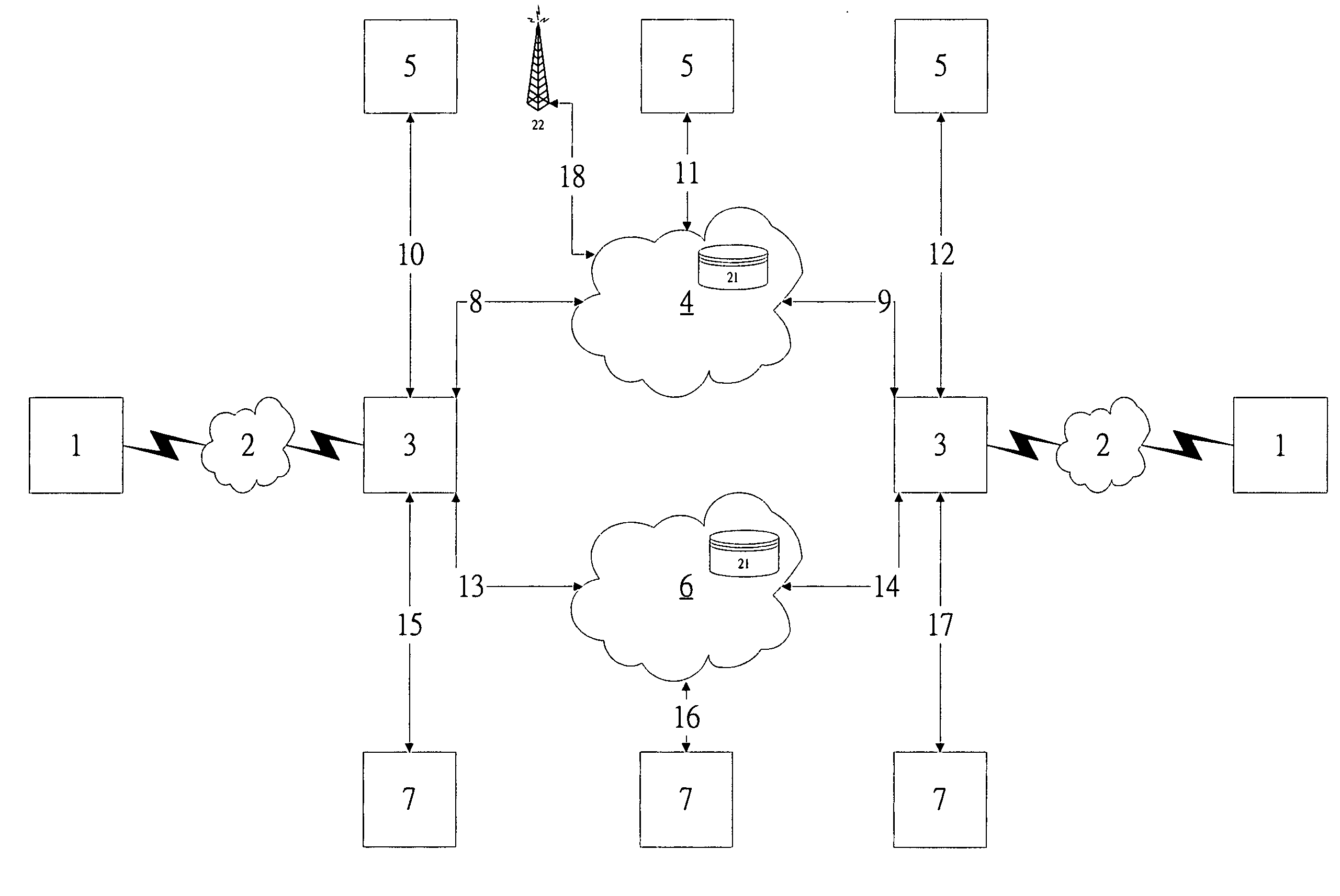
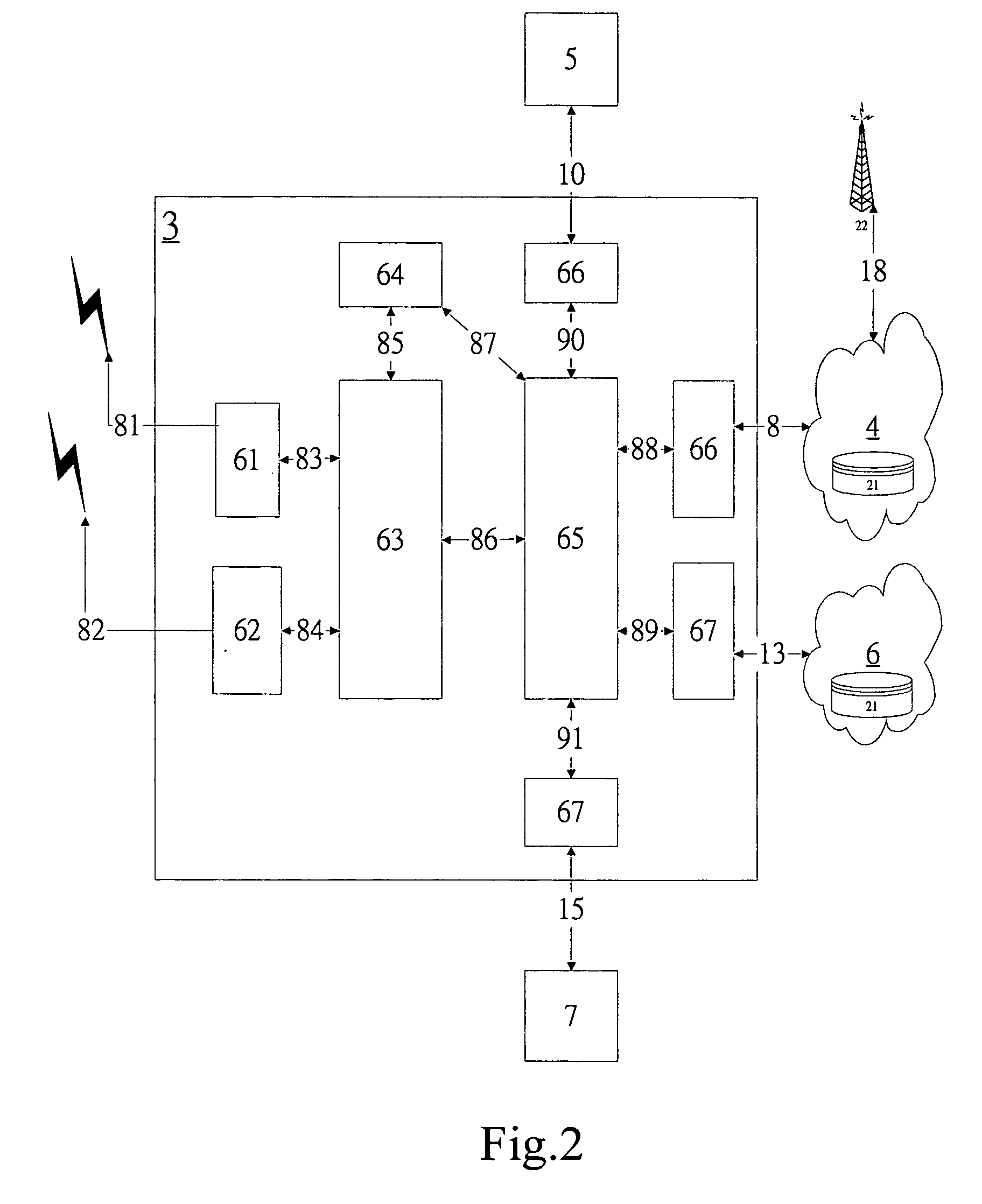
[0032]Firstly, referring to FIG. 1, which shows a schematic system architecture using mobile communication devices 1 and communication network switch devices 3 as primary parties. The communication network switches 3 having telephone numbers connect with cable telephony 5 respectively through line 10 and line 12, and the communication network switch devices 3 connect with a cable telephony network 4 respectively through line 8 and line 9. The communication network sw...


PUM


Abstract

A communication network switch system, comprising: a first phone number database accessed by a cable telephony network service provider; a second phone number database accessed by an internet service provider; a plurality of communication network switch devices conducting audio and / or data communications therebetween through a cable telephony network or an internet, the communication network switch devices switching audio and / or data communications between the cable telephony network or an internet telephony system and a short-range wireless communication network; and a plurality of mobile communication devices each of which including a long-range wireless network system transceiver module, a short-range wireless network system transceiver module and a switch device module. The communication network switch device includes a short-range wireless communication network transceiver module, a cable telephony network transceiver module, an internet telephony system drive module, a first switch module and a second switch module. The first switch module of the communication network switch device stores a communication number of a long-range wireless communication network of the mobile communication device and an assigned phone number of the switch device module in the cable telephony network in the first phone number database. The second switch module of the communication network switch device stores a communication number of a long-range wireless communication network of the mobile communication device and an IP address of the second switch module in the second phone number database.

Description

BACKGROUND OF THE INVENTION[0001]1. Field of the Invention[0002]The present invention relates to a communication network switch device between communication systems, which coordinates with a cable telephony network and an internet to transmit audio and data information. More specifically, the present invention integrates a multitude of short-range wireless network systems (for example Bluetooth wireless network system and 802.11 wireless local area network system, etc.), a cable telephony network and an internet telephony system for communication between two different mobile communication devices which are within power ranges of their own communication network switch devices, and instead of use of a long-range wireless communication system for communication between a mobile communication device and a cable telephony and an internet telephony such that a cable telephony network system and an internet telephony system can be sufficiently employed for communication.[0003]2. Description...

Claims


Application Information

Patent Timeline
Patent Type & Authority Patents(United States)
IPC IPC(8): H04Q7/20H04B7/00H04M1/00H04W48/18H04W88/06
CPCH04W48/18H04W88/06
Inventor CHEN, ALBERTCHIANG, KEH-LIH
Owner MICROCHIP TECH INC
Learn More