
Dual CPP GMR sensor with in-stack bias structure

a bias structure and sensor technology, applied in the field of current perpendicular to plane (cpp) magnetoresistive sensors, can solve the problems of weakening the magnetostatic coupling between the insulation layer, no practical dual cpp gmr sensor has been manufactured, and traditional hard bias layers formed at either side of the sensor, etc., to achieve good antiparallax coupling, strong negative magnetostriction, and strong magnetic anisotropy

Inactive Publication Date: 2008-10-14
HITACHI GLOBAL STORAGE TECH NETHERLANDS BV
View PDF18 Cites 0 Cited by
  • Summary
  • Abstract
  • Description
  • Claims
  • Application Information

AI Technical Summary

Benefits of technology

"The present invention provides a current perpendicular to plane dual magnetoresistive sensor with a novel in stack bias structure. The bias structure includes a plurality of antiparallel coupled magnetic layers at least one of which includes a layer of Ni sandwiched between first and second layers of NiFe. The in stack bias structure allows for a strong magnetic anisotropy in a desired direction parallel with the ABS and provides excellent track width control by avoiding adjacent track interference. The use of an in stack bias structure also avoids the problem of weak magnetostatic coupling and resulting weak biasing efficiency normally associated with the use of a standard hard bias layer formed at the sides of a CPP sensor and separated from the sensors stack by an insulation layer."

Problems solved by technology

As of yet, no practical dual CPP GMR sensor has been manufactured.
This is in part due to the difficulty in aligning the magnetic moments of the free and pinned layers so that they are additive rather than subtractive.
Another challenge to constructing a practical dual CPP GMR is the necessity of having an insulation layer at either side of the sensor.
This insulation layer weakens the magnetostatic coupling between the bias layer and the free layer.
Therefore, traditional hard bias layers, formed at either side of the sensor, are less effective in a CPP sensor.
However, the hard bias layers typically placed at either sides of the sensor do not function as magnetic shields, due to their necessary high coercivity.

Method used


Image

  • Dual CPP GMR sensor with in-stack bias structure
  • Dual CPP GMR sensor with in-stack bias structure
  • Dual CPP GMR sensor with in-stack bias structure

Examples


Embodiment Construction

[0025]The following description is of the best embodiments presently contemplated for carrying out this invention. This description is made for the purpose of illustrating the general principles of this invention and is not meant to limit the inventive concepts claimed herein.

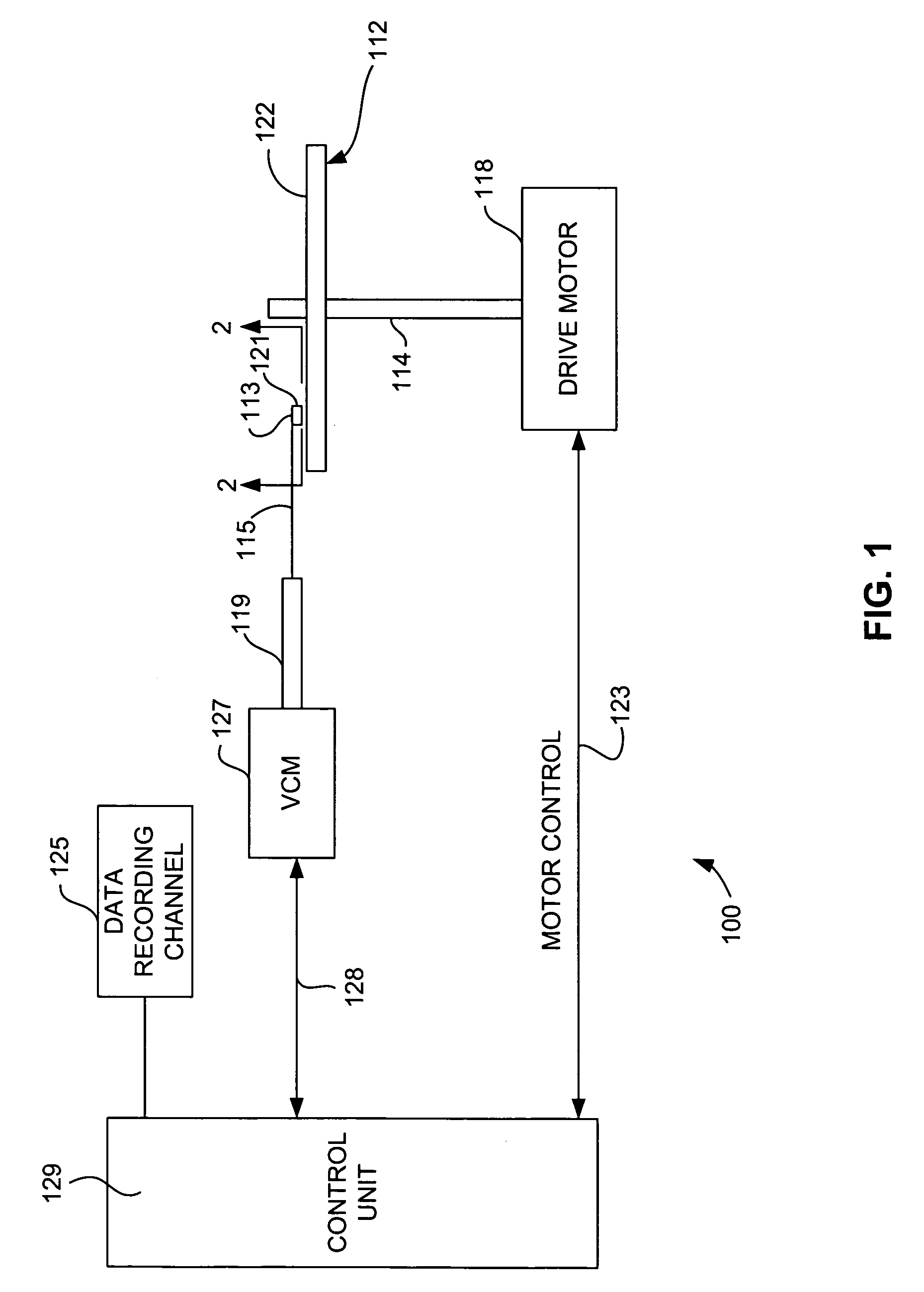
[0026]Referring now to FIG. 1, there is shown a disk drive 100 embodying this invention. As shown in FIG. 1, at least one rotatable magnetic disk 112 is supported on a spindle 114 and rotated by a disk drive motor 118. The magnetic recording on each disk is in the form of annular patterns of concentric data tracks (not shown) on the magnetic disk 112.

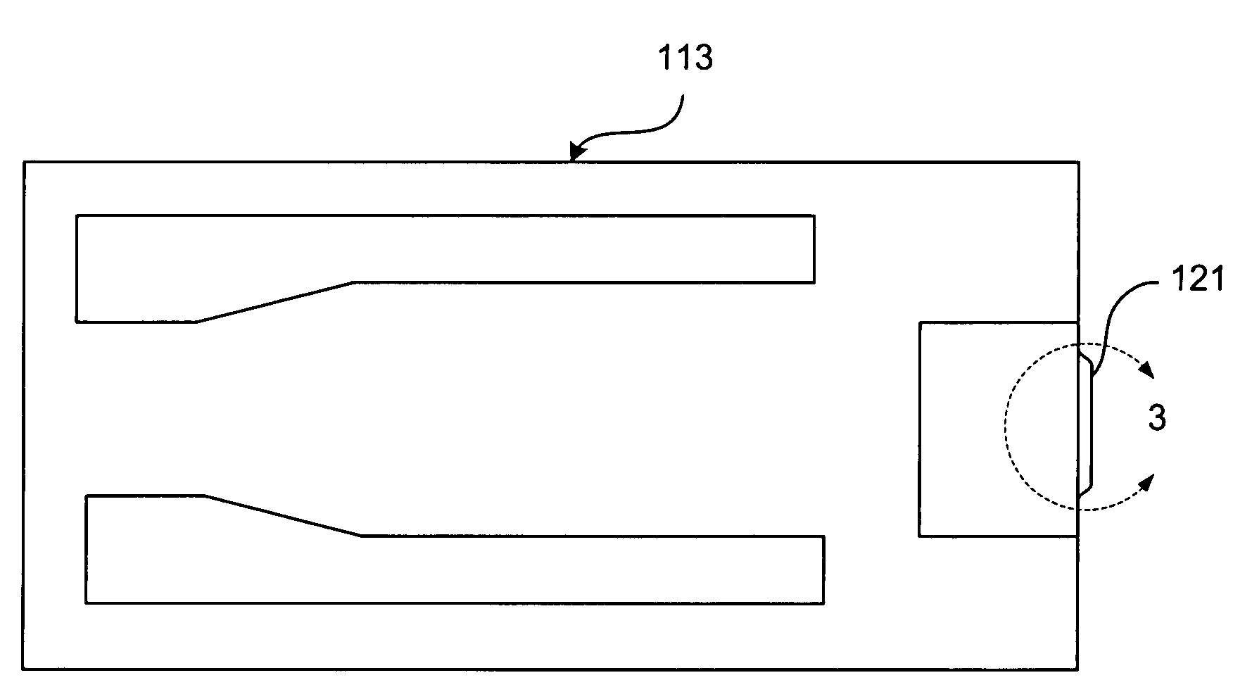
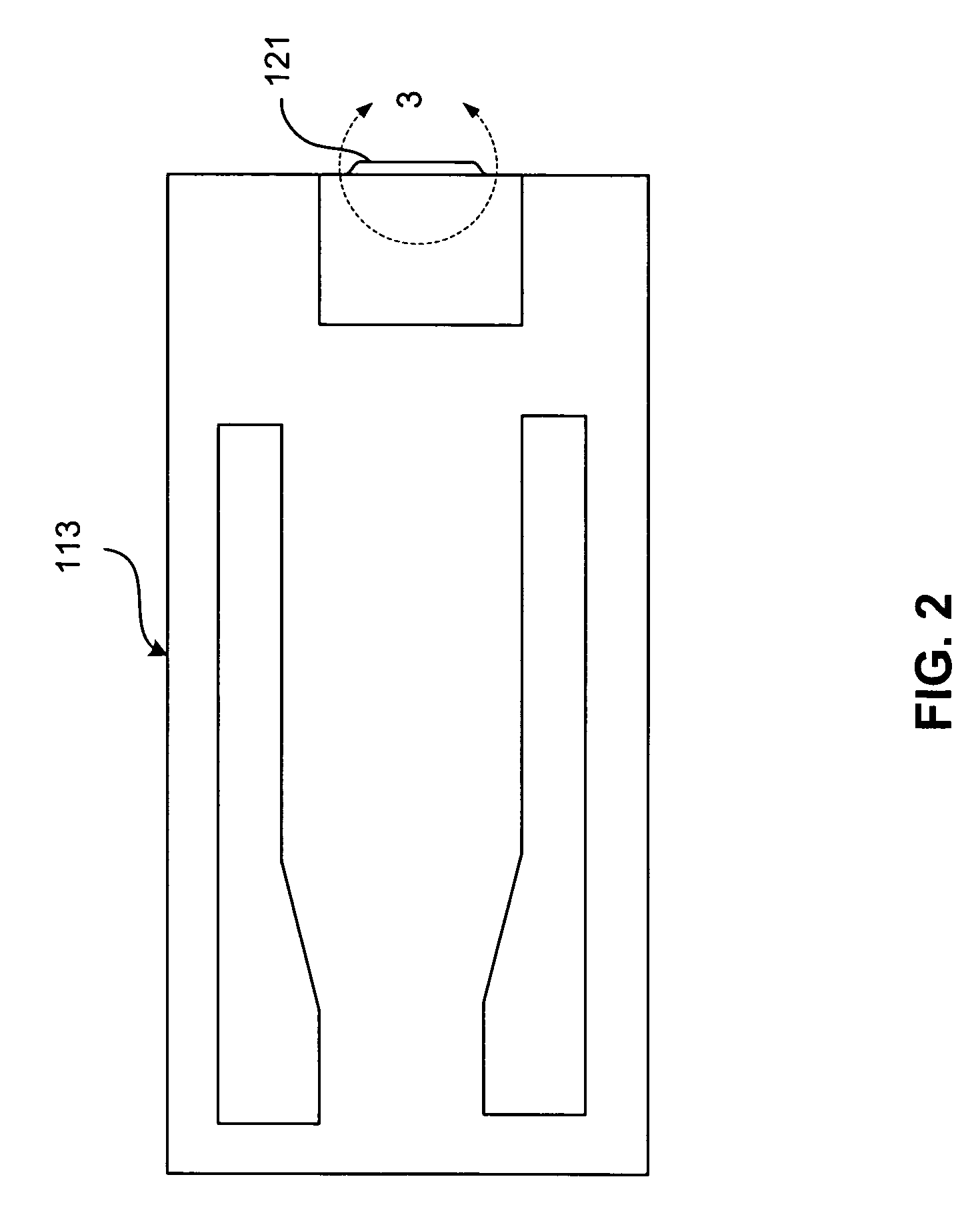
[0027]At least one slider 113 is positioned near the magnetic disk 112, each slider 113 supporting one or more magnetic head assemblies 121. As the magnetic disk rotates, slider 113 moves radially in and out over the disk surface 122 so that the magnetic head assembly 121 may access different tracks of the magnetic disk where desired data are written. Each slider 1...


PUM

PropertyMeasurementUnit
thicknessaaaaaaaaaa
thicknessaaaaaaaaaa
thicknessaaaaaaaaaa

Abstract

A dual current perpendicular to plane (CPP) sensor having an in stack bias structure disposed between first and second free layers. The hard bias structure includes a plurality of magnetic layers antiparallel coupled with one another. At least one of the magnetic layers of the in stack bias structure includes a layer of Ni sandwiched between first and second layer of NiFe. The Ni provides a strong negative magnetostriction that sets the moment of the magnetic layer in a desired direction parallel with the ABS while the NiFe layers at either side of the Ni provide good antiparallel coupling properties, allowing the magnetic layer to be antiparallel coupled with adjacent magnetic layers of the in stack bias structure.

Description

FIELD OF THE INVENTION[0001]The present invention relates to current perpendicular to plane (CPP) magnetoresistive sensors having improved having a novel in stack free layer bias structure that provides improved free layer stability.BACKGROUND OF THE INVENTION[0002]The heart of a computer is an assembly that is referred to as a magnetic disk drive. The magnetic disk drive includes a rotating magnetic disk, write and read heads that are suspended by a suspension arm adjacent to a surface of the rotating magnetic disk and an actuator that swings the suspension arm to place the read and write heads over selected circular tracks on the rotating disk. The read and write heads are directly located on a slider that has an air bearing surface (ABS). The suspension arm biases the slider into contact with the surface of the disk when the disk is not rotating but, when the disk rotates, air is swirled by the rotating disk. When the slider rides on the air bearing, the write and read heads are ...

Claims


Application Information

Patent Timeline
Patent Type & Authority Patents(United States)
IPC IPC(8): G11B5/127
CPCG11B5/3932H01L43/08H10N50/10
Inventor GILL, HARDAYAL SINGH
Owner HITACHI GLOBAL STORAGE TECH NETHERLANDS BV
Learn More