
Device for controlling or regulating auxiliary brake torque in a motor vehicle

a technology of auxiliary brake and motor vehicle, which is applied in the direction of braking system, process and machine control, instruments, etc., can solve the problems of transmission components being exposed to stresses in excess of their maximum torque capacity, high risk of combined brake force, and high cos

Inactive Publication Date: 2008-10-14
VOLVO LASTVAGNAR AB
View PDF7 Cites 7 Cited by
  • Summary
  • Abstract
  • Description
  • Claims
  • Application Information

AI Technical Summary

Benefits of technology

[0018]A foremost advantage of such a device configured according to the teachings of the present invention is that the turning down, or moderation of the auxiliary brakes of the retarder type makes it possible, in the case of at least a hydrodynamic retarder, to economize on the cooling capacity of the engine cooling system. This ultimately extends the duration of an auxiliary braking process entailing a certain total brake torque before the engine cooling system's capacity is exceeded (oils over), and, in the case of an electromagnetic retarder, to avoid unnecessary heating of the retarder. According to the invention, the limit value is determined based on one or more transmission components which have the lowest torque capacity in instance of auxiliary braking. An advantage of this is that the invention ensures that the torque capacity for the vehicle transmission is not exceeded, and hence expensive repairs can be avoided.
[0020]Apart from the above-stated advantage, another advantage of this is that, as a result of the secondary auxiliary brake being moderated first, certain types of transmissions disposed between the engine and the secondary auxiliary brake are guaranteed to be spared from being wrongly subjected to load, a situation which would occur if the primary auxiliary brake were to be moderated first.

Problems solved by technology

When a vehicle is equipped with powerful auxiliary brakes, for example both primary and secondary auxiliary brakes, or a plurality of just the primary type, there is a high risk that the combined brake force is so great that in certain situations some transmission components are exposed to stresses in excess of their maximum torque capacity.
The values are often compromises since it would be too expensive to take into account any specific peculiarities of individual vehicles and specific situations.
Furthermore, there is no feedback utilized in the regulation of the estimation by which the values are verified.
The maximum braking capacity of a retarder can usually be utilized only for relatively short periods, owing to the inadequate capacity of the cooling system.
This can lead to a reduction in braking capacity, at least in the case of lengthy use and maximum utilization of the capacity of the retarder, and even possibly to the total loss, in principle, of the braking capacity.
Vehicles equipped with more than one auxiliary brake often have more brake force at their disposal and therefore run a greater risk of exceeding the torque capacity of some transmission components in case of auxiliary braking.
An example of such a situation is the case in which lengthy auxiliary braking is employed and the retarder utilizes an unnecessarily large amount of the capacity of the cooling system because the braking energy of the retarder has to be dissipated using the vehicle cooling system.
After a relatively short time period, auxiliary braking has to be halted because of overheating of the vehicle's cooling system.
In similar configurations, but where one of the two auxiliary brakes is an electromagnetic retarder, the retarder can become so heated up that there is a risk of a reduction or total loss in braking capacity from the retarder.
This can be a problem if the driver, under such conditions, requests maximum auxiliary brake force from both the auxiliary brakes.
The available brake force will not be sufficient, and this can lead to the service brakes of the vehicle having to be used instead.

Method used


Image

  • Device for controlling or regulating auxiliary brake torque in a motor vehicle
  • Device for controlling or regulating auxiliary brake torque in a motor vehicle
  • Device for controlling or regulating auxiliary brake torque in a motor vehicle

Examples


Embodiment Construction

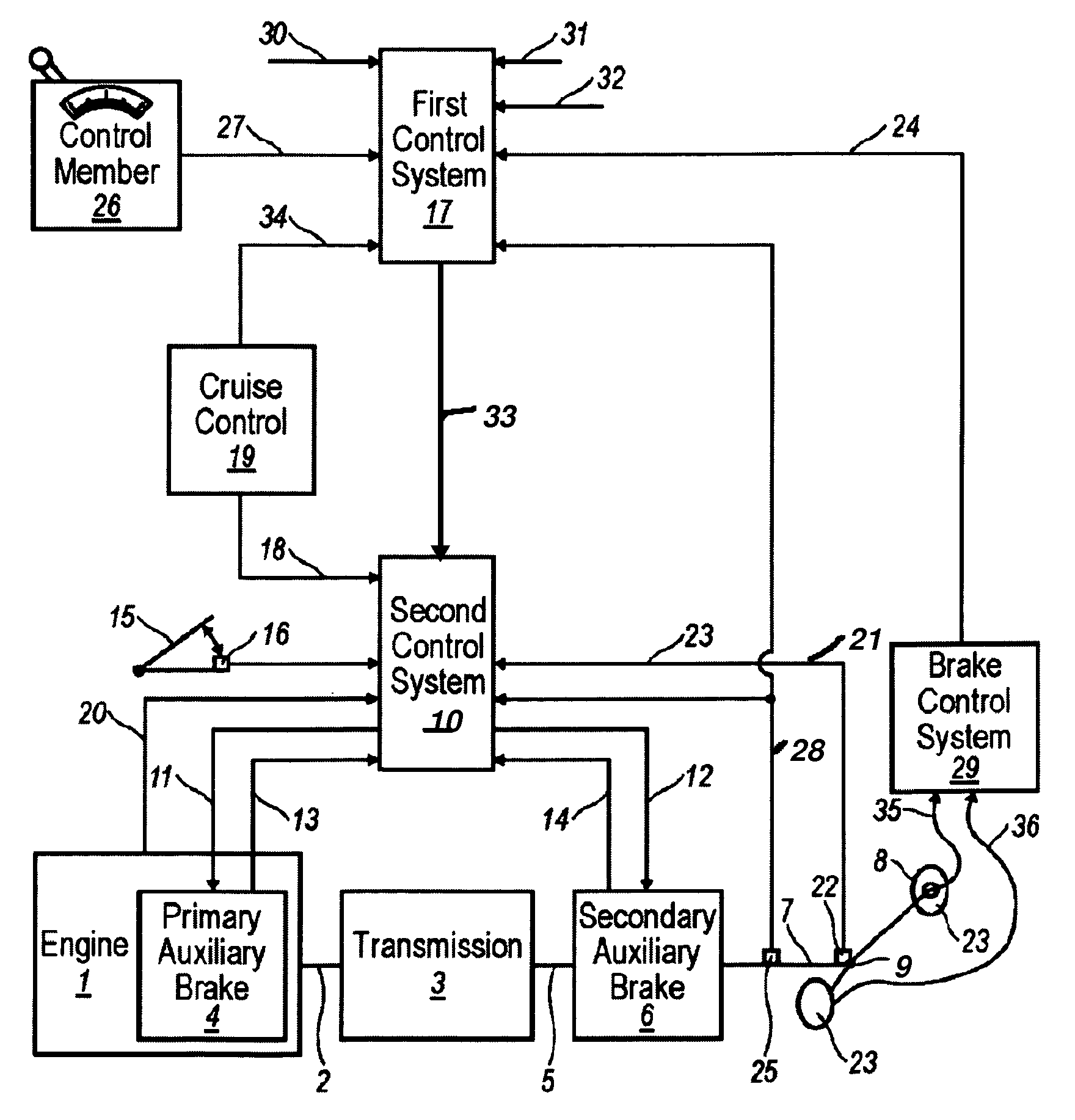
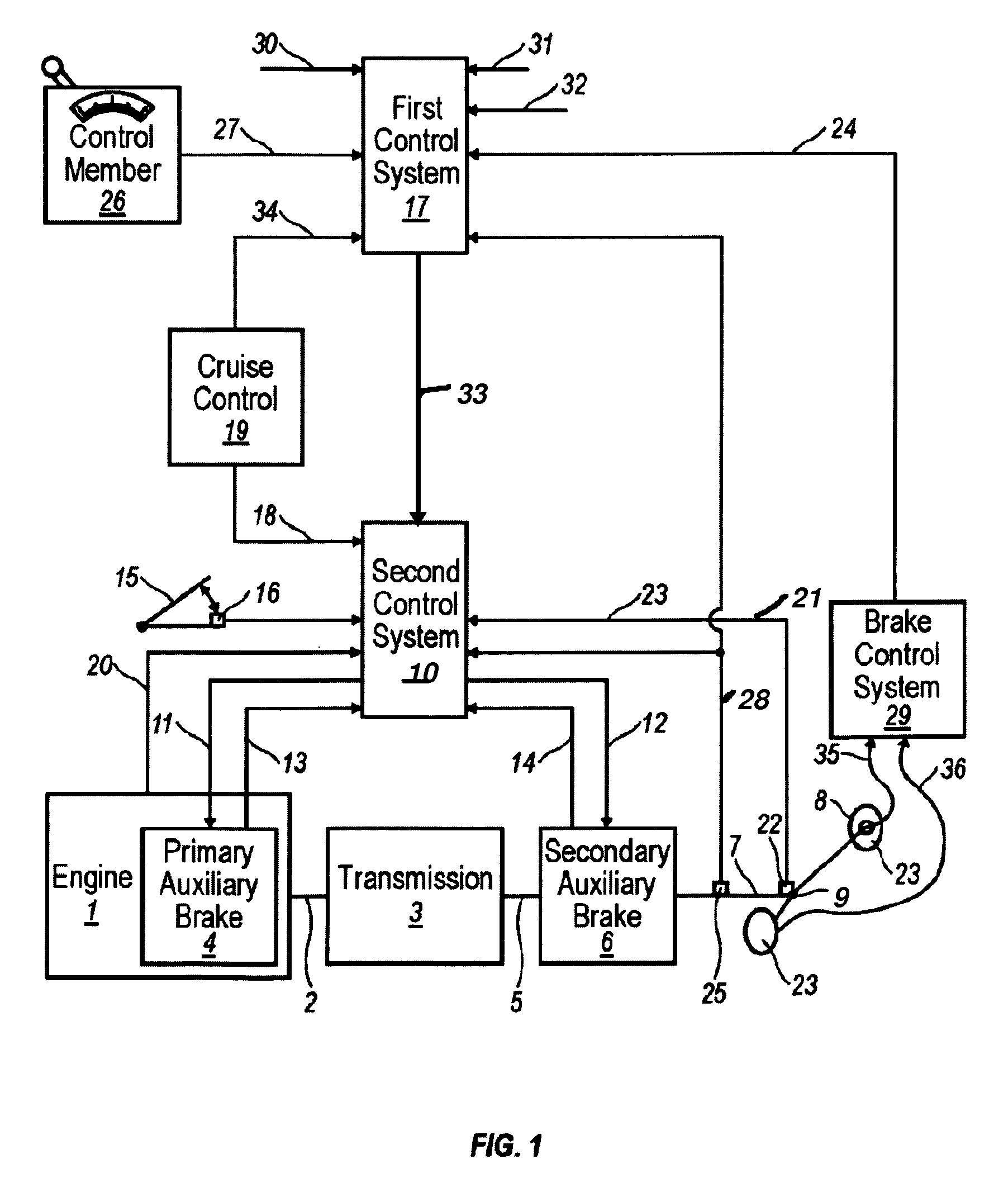
[0026]FIG. 1 shows a diagrammatic representation of a system configured according to the present invention suitable for controlling and / or regulating an auxiliary brake torque in a vehicle. An engine 1 is connected by an output shaft 2 to a transmission 3 which is the main transmission of the vehicle, and which usually offers the possibility of driving the vehicle both forward and in reverse utilizing many different gear ratios between the engine 1 and drive wheels 8. The transmission 3 can be equipped with auxiliary transmissions (for example a splitter transmission or range-change transmission) in order to obtain more drive gears. In the engine 1, a primary auxiliary brake 4 is disposed. It should be noted that the primary auxiliary brakes can also be disposed between the engine 1 and the transmission 3, or in the transmission on its input shaft. An auxiliary brake of, for example, the compression brake-type is disposed in the engine 1. A retarder is usually disposed on the input ...


PUM


Abstract

Method and arrangement for controlling or regulating total auxiliary brake torque in a motor vehicle. The device includes at least one first auxiliary brake (4) of a first type and at least one second auxiliary brake (4, 6) of a second type that is different from the first type. The second auxiliary brake (4, 6) can take the form of a retarder (4, 6). A control system (10, 17) is provided for controlling or regulating the auxiliary brake. Information is stored in the control system regarding characteristics of the respective auxiliary brake (4, 6) and at least one predefined limit value for maximally permitted auxiliary brake torque. The control system (10, 17) is designed such that, if the limit value is exceeded or if a request is made for the brake force from the auxiliary brakes (4, 6) to be moderated, then this is done by turning down or moderating, in the first place, the brake torque of the retarder (6).

Description

CROSS-REFERENCE TO RELATED APPLICATIONS[0001]The present application is a continuation patent application of International Application No. PCT / SE02 / 02460 filed 30 Dec. 2002 which was published in English pursuant to Article 21(2) of the Patent Cooperation Treaty, and which claims priority to both Swedish Application No. 0200222-8 filed 25 Jan. 2002. Said applications are expressly incorporated herein by reference in their entireties.TECHNICAL FIELD[0002]The present invention relates to a device for controlling and / or regulating the total auxiliary brake torque in a vehicle equipped with an engine, drive wheels and transmission components incorporated between the engine and the drive wheels.BACKGROUND ART[0003]It is known to fit auxiliary brakes on a vehicle that is equipped with an engine and drive wheels, with transmission components incorporated therebetween, and which components include a main transmission with which a driver of the vehicle can select different gears for forward ...

Claims


Application Information

Patent Timeline
Patent Type & Authority Patents(United States)
IPC IPC(8): B60T13/74B60T10/02B60T13/58B60T13/66
CPCB60T10/02B60T13/585B60T13/662Y10T477/679Y10T477/644
Inventor SABELSTROM, MATSWALLGREN, HANSZETTERGREN, LARS
Owner VOLVO LASTVAGNAR AB
Learn More