
Thyristor power converter filter for excitation applications

a technology of power converter and filter, applied in the direction of electric generator control, pulse technique, instruments, etc., can solve the problems of device turning on without a gating signal at an unintended time, excessive temperature, and device failure, etc., to reduce complexity, components and cost

Active Publication Date: 2008-10-07
GENERAL ELECTRIC CO
View PDF6 Cites 6 Cited by
  • Summary
  • Abstract
  • Description
  • Claims
  • Application Information

AI Technical Summary

Benefits of technology

The present invention provides an apparatus and method for protecting components of a thyristor power converter for excitation applications. The invention includes a three-phase AC line filter and bleed resistors to handle AC input transients, thyristor switching transients, and deenergized AC input. The invention also includes an exciter system with a thyristor in each leg of a three-phase bridge and a three-phase AC line filter with bleed resistors for better protection. The technical effects of the invention include improved safety and reliability of thyristor power converters for excitation applications.

Problems solved by technology

If the rate of rise of anode current is very fast, localized heating will occur due to high current density, resulting in excessive temperature and possible failure of the device.
Exceeding maximum dv / dt across a thyristor may cause the device to turn on without a gating signal at an unintended time.
All of these filtering components together typically exceed the cost of the thyristors themselves.
Early thyristors were fragile and needed good protection, so significant conservatism was incorporated in the design.
Incorporation of all the above protective features provides reliable operation and highly protected components, but results in increased material and labor costs.
This results in high stress in the capacitor.
Sizing the diode bridge to handle the high voltages and current peaks can make this an expensive approach.
In addition, the diodes also have recovery charges, which result in additional transient disturbances to the system.
Reliability is lower due to the higher failure rates of active diodes compared to passive designs.

Method used


Image

  • Thyristor power converter filter for excitation applications
  • Thyristor power converter filter for excitation applications
  • Thyristor power converter filter for excitation applications

Examples


Embodiment Construction

[0025]The following embodiments of the present invention have many advantages, including reduced complexity, fewer components and lower cost. At the same time, reliability is improved.

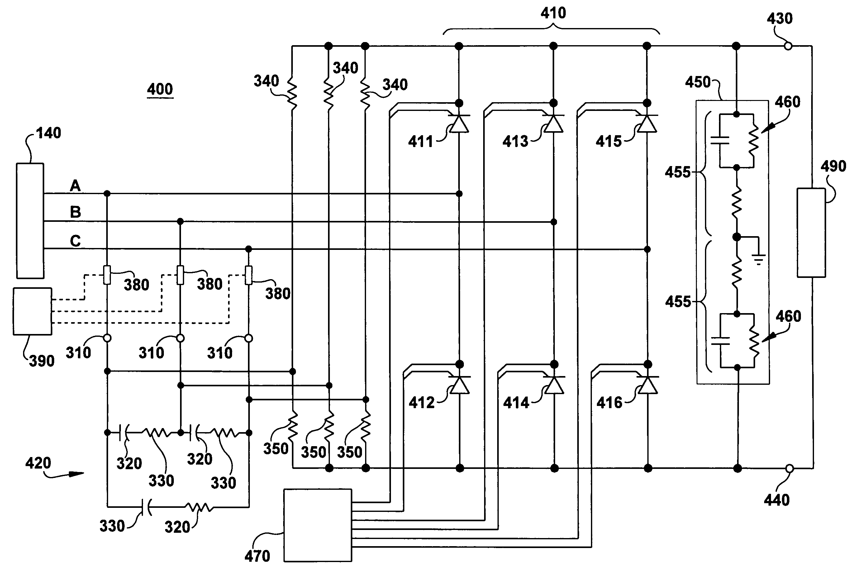
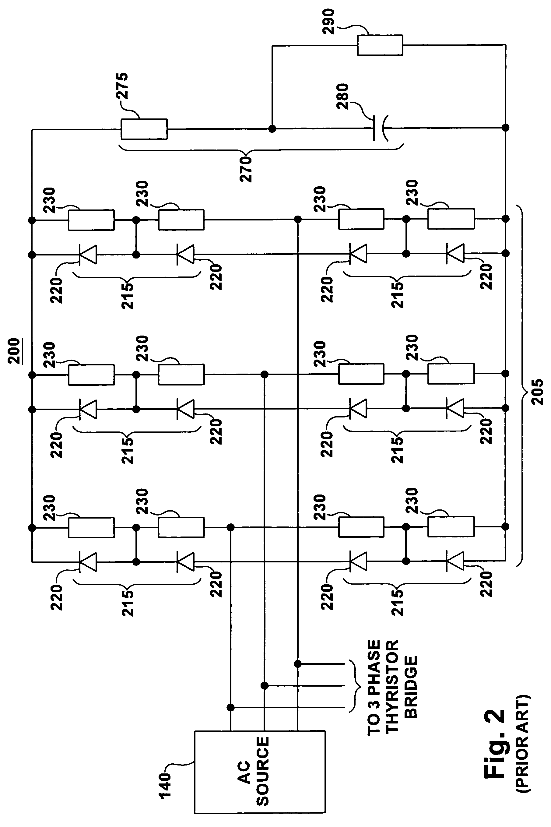
[0026]One aspect of the present invention provides a three-phase input AC filter circuit, which provides protection for the components of the three-phase thyristor bridge circuit with a reduced amount of bridge filtering components compared to conventional practice. In particular, RC snubbers in parallel with the thyristors and ferrite inductors in series with the thyristors have been eliminated. This configuration instead relies on a three-phase AC line filter to absorb thyristor recovery energy and to protect the thyristors and other system components from excessive voltage and current gradients and voltage levels.

[0027]Some prior art applications, which were originally designed as power converters for drive applications, have been directly reused for excitation applications, without consideration of...


PUM


Abstract

An exciter system for the field of a synchronous generator excitation is provided. The exciter system includes an AC power source; a three-phase thyristor bridge having six legs, the three-phase bridge being connectable with the AC power source, and being adapted to provide a variable DC voltage output; a thyristor in each of the six legs of the three-phase bridge, wherein the thyristors provide a path for a device current; and a three-phase AC line filter series, including series resistive and capacitive elements across each phase of the AC power source and a plurality of bleed resistors, wherein at least one bleed resistor is connected to each AC input connection of the filter.

Description

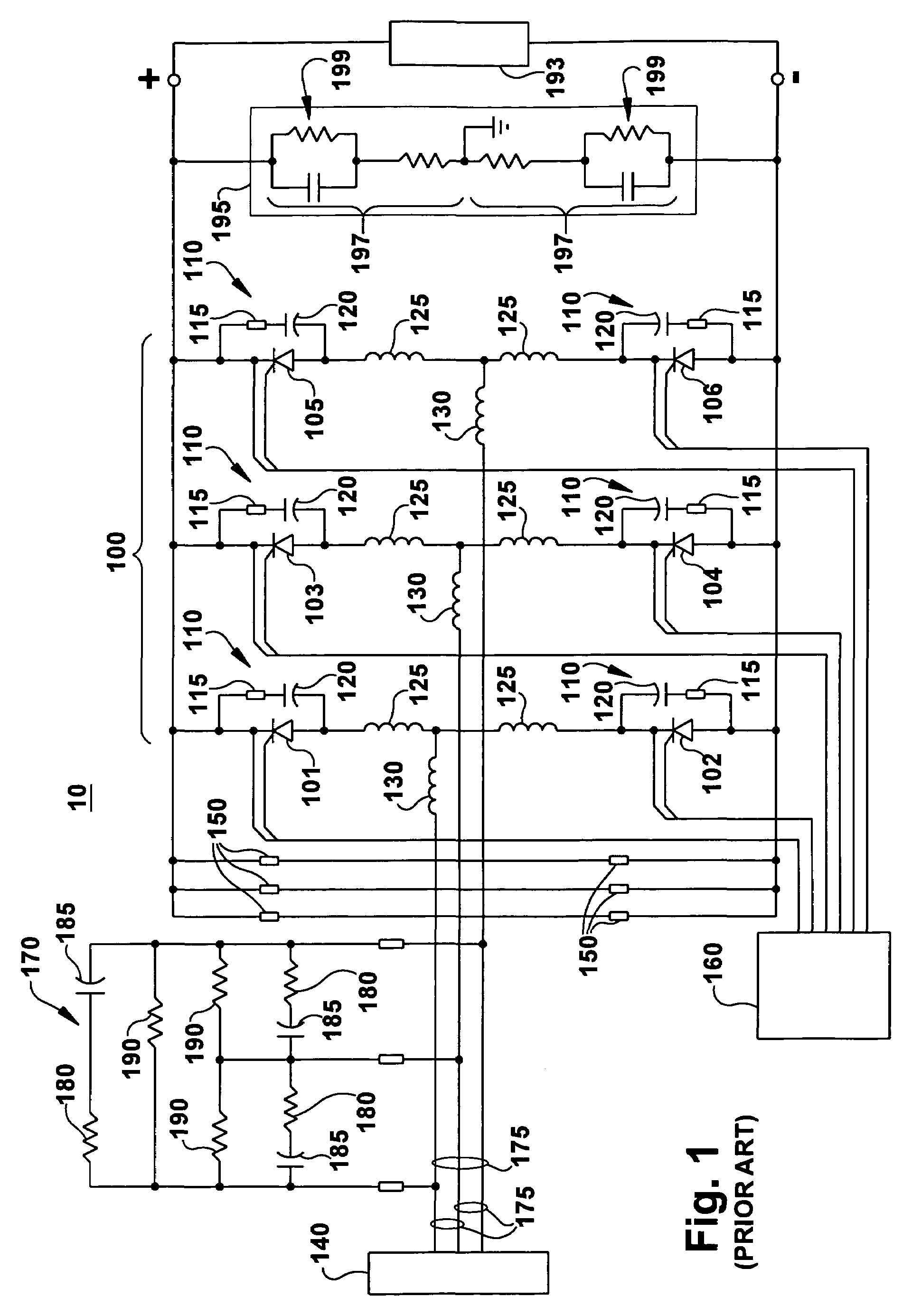
BACKGROUND OF THE INVENTION[0001]The invention relates generally to an apparatus and method for converting AC voltage to a variable DC voltage and more specifically to an apparatus for converting AC voltage to a variable DC voltage for exciting the field windings of electrical generating equipment.[0002]It has been common practice to use a full thyristor bridge to convert AC voltage to a variable DC voltage for exciting the rotating field of a synchronous generator. A typical example of an exciter 10, employing such a full thyristor bridge, is shown in FIG. 1. The full thyristor bridge 100 includes six thyristors 101-106, one connected in each of six legs of the bridge. A full thyristor bridge circuit includes many advantages such as the ability to transiently invert field voltage to rapidly decrease generator field flux linkages.[0003]Conventional phase-controlled thyristor power converters (“bridges”) have been used in DC motor drive and generator excitation supplies for several d...

Claims


Application Information

Patent Timeline
Patent Type & Authority Patents(United States)
IPC IPC(8): H02M1/12
CPCH02P9/105H03K17/08108H03K17/16H03K17/72
Inventor CASTEEL, JORDAN B.BITTNER, JOHN E.
Owner GENERAL ELECTRIC CO
Learn More