
Ambiguity estimation of GNSS signals for three or more carriers

a technology of ambiguity estimation and gnss signals, applied in satellite radio beaconing, measurement devices, instruments, etc., can solve the problems of important cost, weight and run-time factors, and achieve the effects of reducing the effort required for statistical search, high computational efficiency, and reduced validation

Active Publication Date: 2008-10-07
TRIMBLE NAVIGATION LTD
View PDF6 Cites 127 Cited by
  • Summary
  • Abstract
  • Description
  • Claims
  • Application Information

AI Technical Summary

Benefits of technology

[0036]Computationally efficient techniques are employed for obtaining good approximations of the carrier phase ambiguities for three or more frequency bands, greatly reducing the effort required for statistical search and validation is greatly reduced.
[0037]Advantages of embodiments in accordance with the invention as compared to existing multi-carrier ambiguity resolution techniques include high computational efficiency for the filter components (float solution) and the ability to obtain a better knowledge of the error properties of individual measurements and measurement combinations. This efficiency offers one or more benefits. Less-performant processing components are required, enabling construction of receivers at lower cost and / or which consume less power. Even if the processing power is available, most modern CPUs allow saving power by reducing the processor clock and / or putting the processing unit in a kind of sleep mode while no computations are pending. This is an important cost, weight and run-time factor. And for a given processing power, embodiments in accordance with the invention enable use of better computational models than is possible with prior techniques, leading to improved system performance.

Problems solved by technology

This is an important cost, weight and run-time factor.

Method used


Image

  • Ambiguity estimation of GNSS signals for three or more carriers
  • Ambiguity estimation of GNSS signals for three or more carriers
  • Ambiguity estimation of GNSS signals for three or more carriers

Examples


coefficient example

[0234]The following example specifies the coefficients for the four-carrier case.

Minimum-Error Geometric Carrier-Phase Combination

[0235]The minimum-error carrier-phase combination is used in the geometric float-solution filter. The carrier-phase combination used there is defined as:

[0236]φgeo=a→geoT·(ϕ1ϕ2ϕ3ϕ4)=(ageo,1ageo,2ageo,3ageo,4)T·(ϕ1ϕ2ϕ3ϕ4)(0.71)

[0237]With the following notations:

[0238]B⇀geo=-λ1·(1λ21λ31λ4)(0.72)Qgeo=(σϕ22000σϕ32000σϕ42)(0.73)R⇀geo=1λ1·B⇀geo+(λ2λ12λ3λ12λ4λ12)(0.74)

in which the coefficients are defined by:

[0239](ageo,2ageo,3ageo,4)=-(σϕ12·B⇀geo·B⇀geoT+Qgeo+σio2·R⇀geo·R⇀geoT)-1·⁢⁢(σϕ12·λ1·B⇀geo+σio2·R⇀geo)(0.75)ageo,1=λ1+B⇀geoT·(ageo,2ageo,3ageo,4)(0.76)

Minimum-Error Ionospheric Carrier-Phase Combination

[0240]The minimum-error ionospheric carrier-phase combination is used in the ionosphere filters. The combination is defined as:

[0241]φiono=a⇀ionoT·(ϕ1ϕ2ϕ3ϕ4)=(aiono,1aiono,2aiono,3aiono,4)T·(ϕ1ϕ2ϕ3ϕ4)(0.77)

[0242]With the following notations:

[0243]A⇀iono=(1λ11λ2...


PUM


Abstract

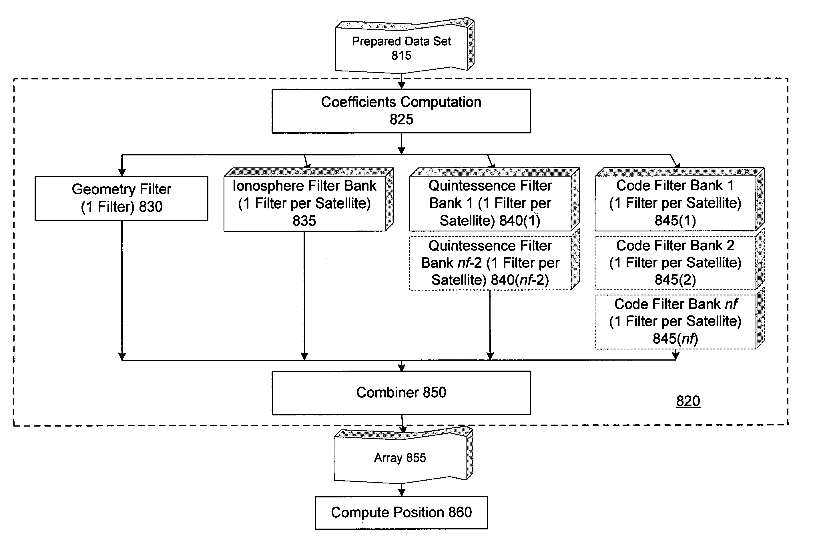
Methods and apparatus are provided for factorized processing of a set of GNSS signal data derived from signals having at least three carriers. A geometry filter is applied to the set of GNSS signal data using a geometry carrier-phase combination to obtain an array of ambiguity estimates for the geometry carrier-phase combination and associated statistical information. A bank of ionosphere filters is applied to the set of GNSS signal data using a geometry-free ionosphere carrier-phase combination to obtain an array of ambiguity estimates for the ionosphere carrier-phase combination and associated statistical information. At least one bank of Quintessence filters is applied to the set of GNSS signal data using a geometry-free and ionosphere-free carrier-phase combination to obtain an array of ambiguity estimates for the geometry-free and ionosphere-free carrier-phase combination and associated statistical information. At least one code filter is applied to the set of GNSS signal data using a plurality of geometry-free and ionosphere-free code-carrier combinations to obtain an array of ambiguity estimates for the code-carrier combinations and associated statistical information. The resulting arrays are combined to obtain a combined array of ambiguity estimates for all carrier phase observations and associated statistical information.

Description

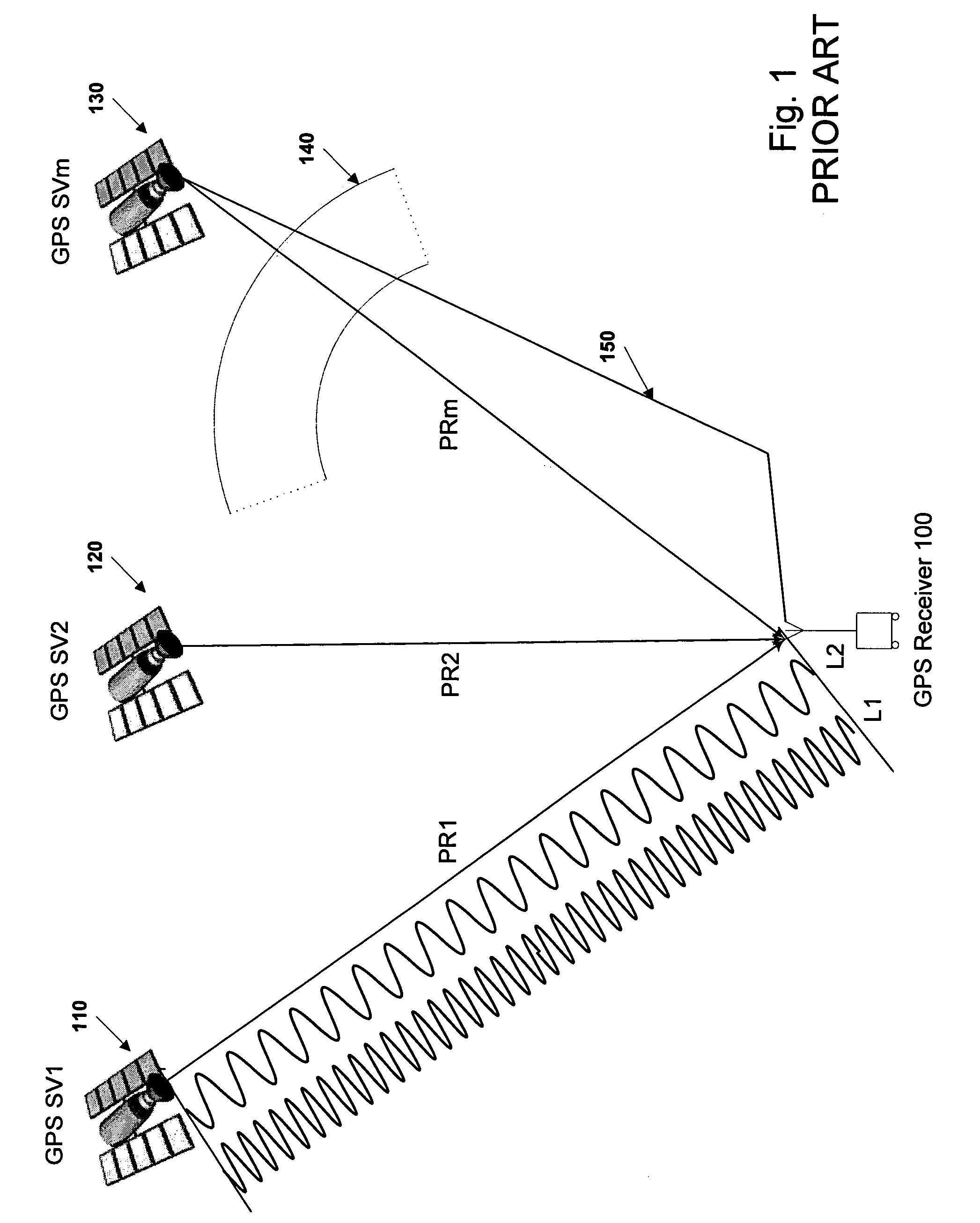
FIELD OF THE INVENTION[0001]The present invention relates to the field of Global Navigation Satellite Systems. More particularly, the present invention relates to ambiguity estimation of GNSS signals for three or more carriers.BACKGROUND[0002]Global Navigation Satellite Systems (GNSS) include the Global Positioning System (GPS), Glonass, and the proposed Galileo system.[0003]Each GPS satellite transmits continuously using two radio frequencies in the L-band, referred to as L1 and L2, at respective frequencies of 1575.42 MHz and 1227.60 MHz. Two signals are transmitted on L1, one for civil users and the other for Department of Defense (DoD) authorized users. One signal is transmitted on L2, intended only for DoD authorized users. Each GPS signal has a carrier at the L1 or L2 frequency, pseudo-random noise (PRN) codes, and satellite navigation data. Two different PRN codes are transmitted by each satellite: a coarse / acquisition (C / A) code and a precision (P / Y code) which is encrypted....

Claims


Application Information

Patent Timeline
Patent Type & Authority Patents(United States)
IPC IPC(8): G01S5/14G01S19/32G01S19/42G01S19/44
CPCG01S19/44G01S19/32
Inventor VOLLATH, ULRICH
Owner TRIMBLE NAVIGATION LTD
Learn More