Anchor device to relieve tension from the rope socket prior to perforating a well

a technology of rope socket and anchor device, which is applied in the direction of tubing catchers, borehole/well accessories, fluid removal, etc., can solve the problems of unbalanced forces applied to perforating guns, all previously developed devices suffer, and the situation is not balanced

Inactive Publication Date: 2008-10-07
BAKER HUGHES INC
View PDF27 Cites 14 Cited by
  • Summary
  • Abstract
  • Description
  • Claims
  • Application Information

AI Technical Summary

Benefits of technology

[0018]This embodiment of the anchoring sub of claim 1 further comprises a wireline connection at its first end and second end thereby providing wireline communication through the anchoring sub. The vertical orientation of the anchoring sub is reversible such that when the slip cone is positioned above the slip assembly and when the slip assembly contacts the slip cone thereby causing the slip assembly to engage the wellbore inner radius. The anchoring sub is prevented from downward movement within the wellbore, and when the slip cone is positioned below the slip assembly and when the slip assembly contacts the slip cone thereby causing the slip cone to engage the wellbore inner radius, the anchoring sub is prevented from upward movement within the wellbore.

Problems solved by technology

When the wellbore pressure is greater than the formation pressure this is known as an overbalanced situation, whereas when the formation pressure exceeds the wellbore pressure is known as an underbalanced situation.
Many times when the perforating guns are detonated, the forces applied to the perforating guns are not balanced and can produce a resultant force that thrusts the perforating gun suddenly upward or downward upon detonation.
This can be exacerbated in an overbalanced or underbalanced condition.
However all of the previously developed devices suffer from one or more of the following disadvantages.
For example, electrical or hydraulically activated anchors are susceptible to problems with reliability, and none of the above noted devices is capable of resetting its anchor should the perforating gun receive an impulse from an unexpected direction.
However if the forces from the individual jets fired from the perforating gun produce a resultant upward force onto the perforating gun, the anchor can become unseated.
If the anchor becomes unseated, the perforating gun will be thrust upward for some distance and then begin to fall, unsupported, within the wellbore.

Method used


Image

  • Anchor device to relieve tension from the rope socket prior to perforating a well
  • Anchor device to relieve tension from the rope socket prior to perforating a well
  • Anchor device to relieve tension from the rope socket prior to perforating a well

Examples


Embodiment Construction

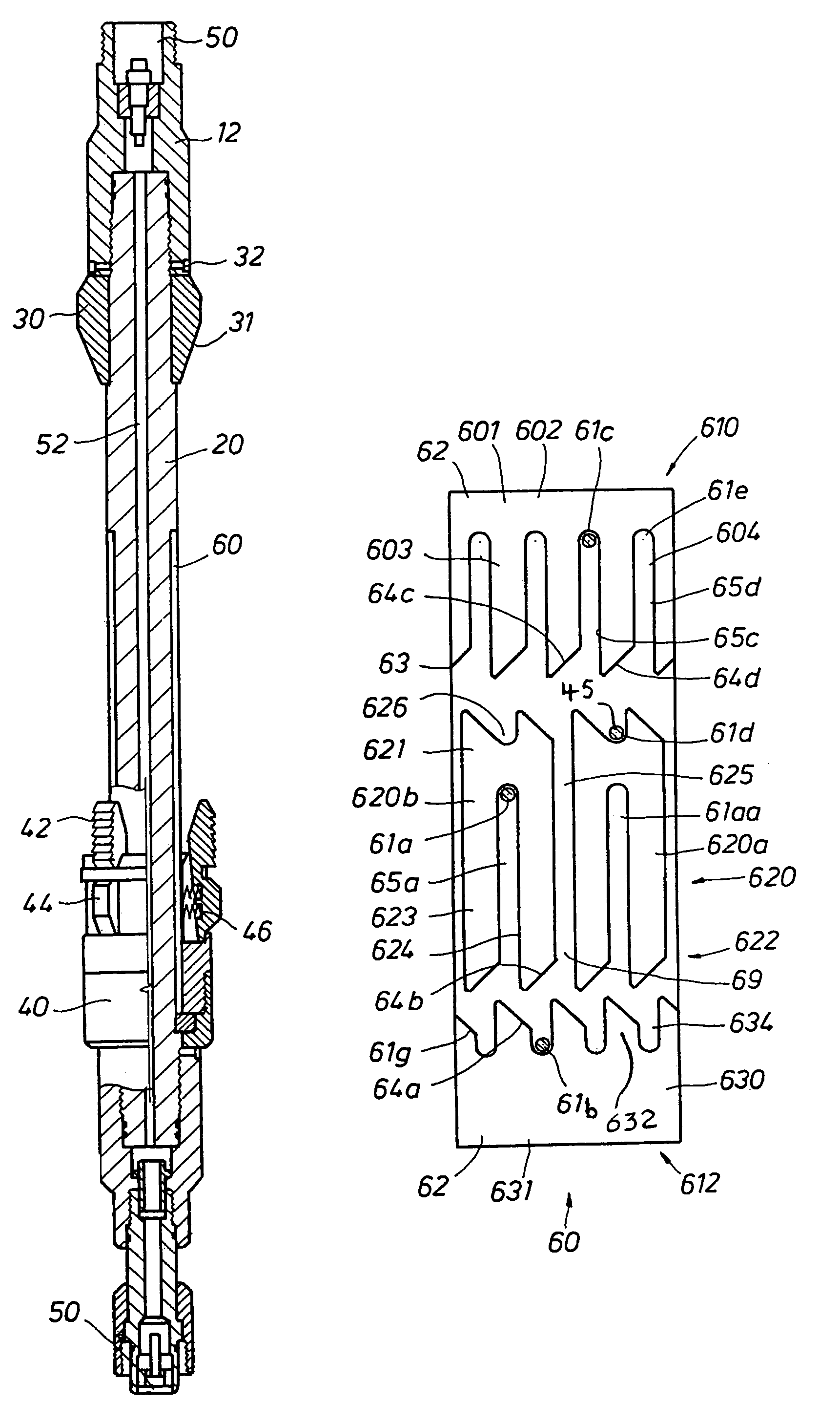
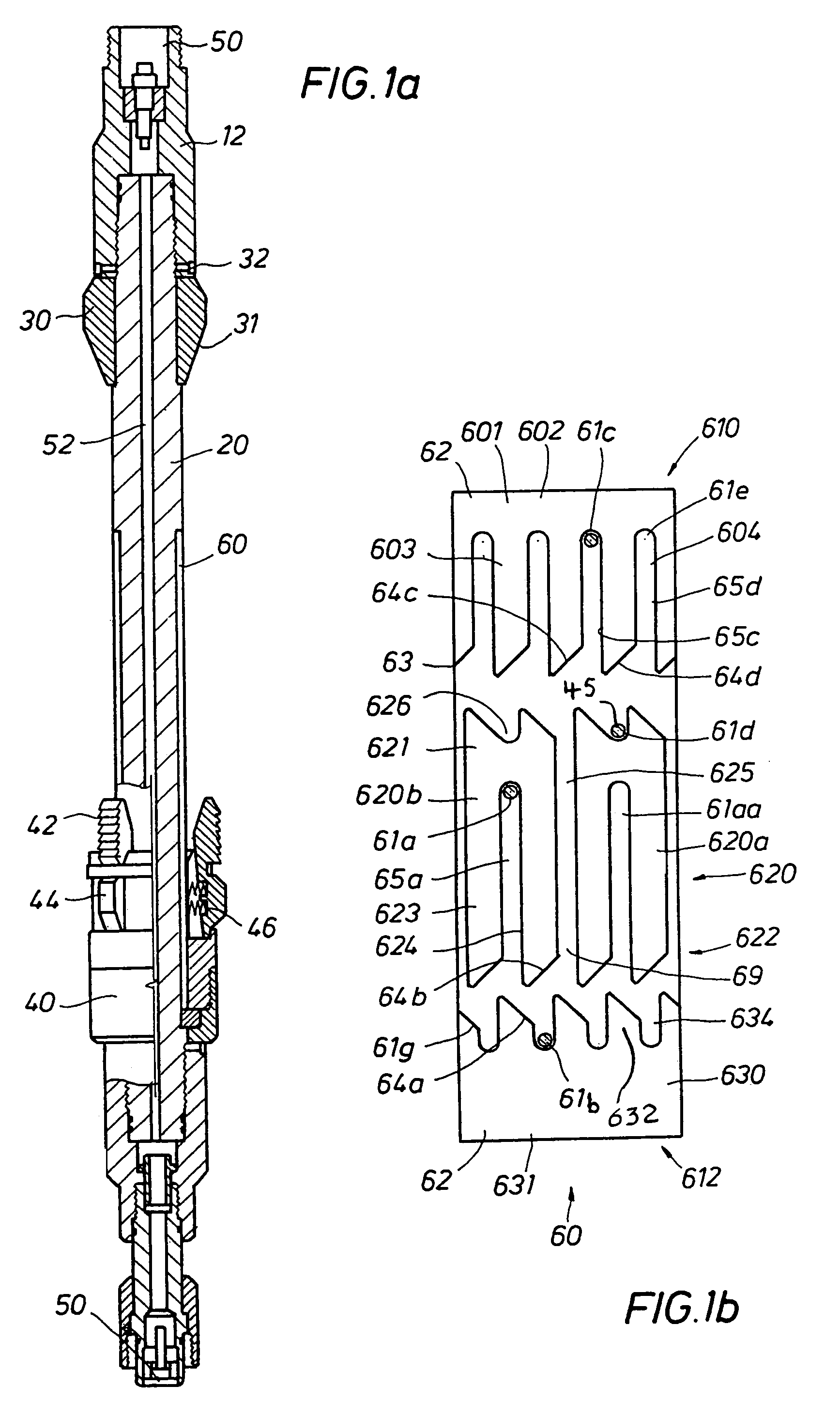
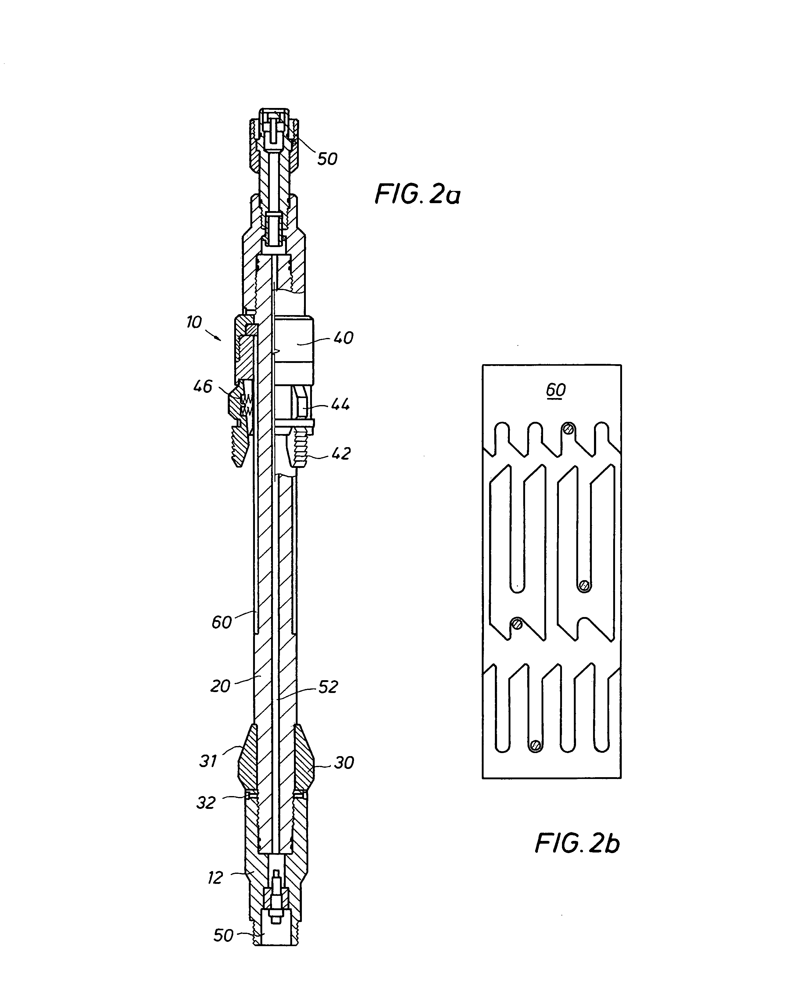
[0026]For the purposes of clarity, directional references with respect to the present invention have been indicated in relation to the surface of the earth. Therefore in describing the present invention, the term “upper” means closer to the surface, whereas the terms “lower” and “below” mean further from the surface. With reference to the drawing herein, an anchoring sub 10 is shown in FIG. 1. This embodiment of the invention comprises a mandrel 20, a slip cone 30, and a slip assembly 40. It is preferred that the mandrel 20 be cylindrical and elongated such that it is suitable for insertion into a hydrocarbon producing wellbore. However other shapes and forms for the mandrel 20 are considered as possible alternative embodiments as long as they perform the required function. Affixed to one end of the mandrel 20 is a slip cone 30 that is beveled on its lower end 31 and terminates on its upper end 32 with a connection to the sub upper connection 12.

[0027]To accommodate the addition of ...


PUM


Abstract

An anchoring sub used in combination with hydrocarbon exploration and production tools, such as perforating guns and logging devices, within a wellbore. The anchor sub is reversible and includes a mandrel, a slip assembly and a slip cone, where the slip assembly selectively travels up and down the mandrel and is able to mate with the slip cone. The anchor sub secures itself to the inner circumference of a wellbore when the slip assembly is mated with the slip cone. Mating and de-mating of the slip assembly with the slip cone is accomplished by selective up and down movement of the anchor sub.

Description

RELATED APPLICATIONS[0001]This application claims priority from co-pending U.S. Provisional Application No. 60 / 433,671, filed Dec. 16, 2002, the full disclosure of which is hereby incorporated by reference herein.BACKGROUND OF THE INVENTION[0002]1. Field of the Invention[0003]The invention relates generally to the field of exploration and production of hydrocarbons from wellbores. More specifically, the present invention relates to a method and apparatus to position and secure production and exploration tools within a wellbore.[0004]2. Description of Related Art[0005]Perforating guns are used for the purpose, among others, of making hydraulic communication passages, called perforations, in wellbores drilled through earth formations so that predetermined zones of the earth formations can be hydraulically connected to the wellbore. Perforations are needed because wellbores are typically completed by coaxially inserting a pipe or casing into the wellbore, and the casing is retained in ...

Claims


Application Information

Patent Timeline
Patent Type & Authority Patents(United States)
IPC IPC(8): E21B43/119E21B23/01E21B40/00E21B23/00E21B43/11
CPCE21B23/006E21B23/01E21B43/11
Inventor WRIGHT, ALPHIEKAISER, GARRY
Owner BAKER HUGHES INC
Why Eureka
Try Eureka