
In-vehicle player

a technology for in-vehicle players and cushion members, which is applied in the field of in-vehicle players, can solve the problems of in-vehicle players suffering from violent violations and impacts, troublesome handling, and discs cannot be exchanged from inside the passenger compartment, so as to achieve the effect of suppressing the influence of vibration and impacts transmitted from the vehicle, maintaining the viscosity of the cushion member for a long time, and reducing the size of the cushion member

Inactive Publication Date: 2008-09-23
SONY CORP +1
View PDF18 Cites 2 Cited by
  • Summary
  • Abstract
  • Description
  • Claims
  • Application Information

AI Technical Summary

Benefits of technology

[0015]The present invention hence has been proposed in view of the situation of related techniques as described above and it is desirable to provide an in-vehicle player capable of suppressing influences of vibrations and impacts transmitted from a vehicle and capable of further downsizing and cost down.
[0017]As described above, in the in-vehicle player according to the present invention, elastic deformation of the cushion member inserted between the outer housing and the two side surfaces of the device body can be utilized to damp appropriately vibrations and impacts transmitted through the outer housing to the device body.
[0018]In addition, the viscous elastic material forming the cushion member can be stuck directly to the mount surfaces of the device body and the outer housing. Therefore, assembly work to attach the cushion member between the outer housing and the two side surfaces of the device body is easy. In addition, the viscosity of the cushion member can be maintained for a long period. Therefore, the cushion member can be stably maintained between the outer housing and the two side surfaces of the device body. Further, the cushion member can be downsized.
[0019]Accordingly, in the in-vehicle player, influences of vibrations and impacts transmitted from the vehicle are suppressed. As a result, operational reliability of the device body during driving of the vehicle can be improved greatly, and further downsizing and cost reduction can be achieved.

Problems solved by technology

In this case, however, the discs cannot be exchanged from inside of the passenger compartment.
To exchange discs in magazine cases, the magazine cases must once be detached from the device body, resulting in troublesome handling.
Meanwhile, these in-vehicle players suffer from violent violations and impacts which are unique to in-vehicle environments, e.g., vertical vibrations transmitted from road surfaces during driving of vehicles, forward and backward vibrations due to acceleration and deceleration of vehicles, etc.
Also, the in-vehicle players each has to be set in a limited mount space in a dashboard as described above, and therefore have to be severely restricted in height dimension.
Consequently, these in-vehicle players have a very strong possibility that discs or the like are brought into contact with internal mechanisms due to vibrations transmitted from vehicles and are thereby damaged.
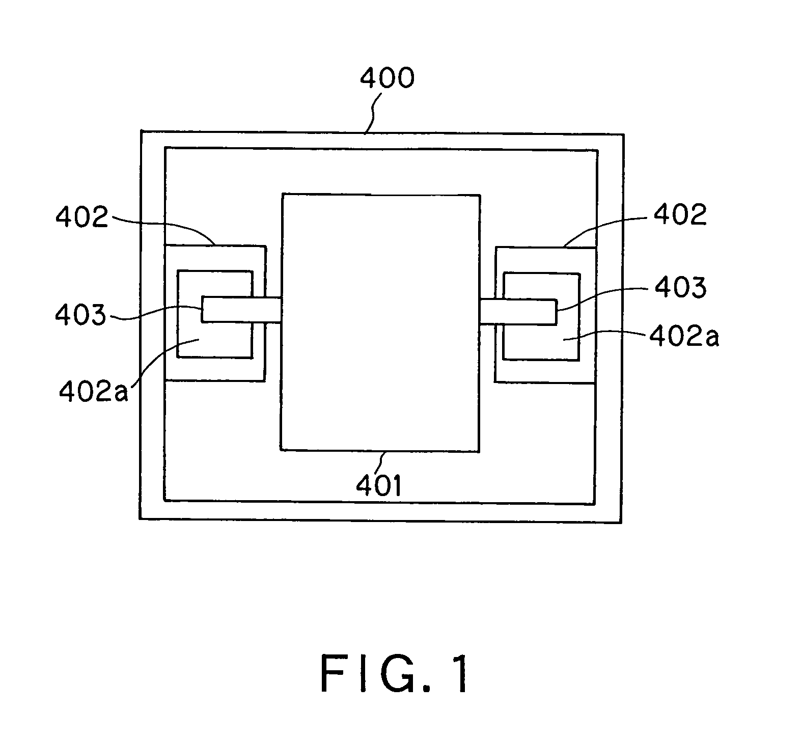
However, if this liquid-sealing damper 402 is used, the inner liquid 402a may leak and hence requires a sealing structure to prevent leakage of the liquid.
As a result, the manufacturing process is complicated, and the damper itself has a larger size.
In addition, since the stirrer shafts 403 are required to stir the liquid 402a, the number of components increases to raise manufacturing costs.
However, it is not taken in consideration to be used in the in-vehicle environments.
Thus, it is difficult to damp vibrations and impacts transmitted from the vehicle to the device body 1.

Method used


Image

  • In-vehicle player
  • In-vehicle player
  • In-vehicle player

Examples


Embodiment Construction

[0068]An in-vehicle player to which the present invention is applied will now be described in details with reference to the drawings.

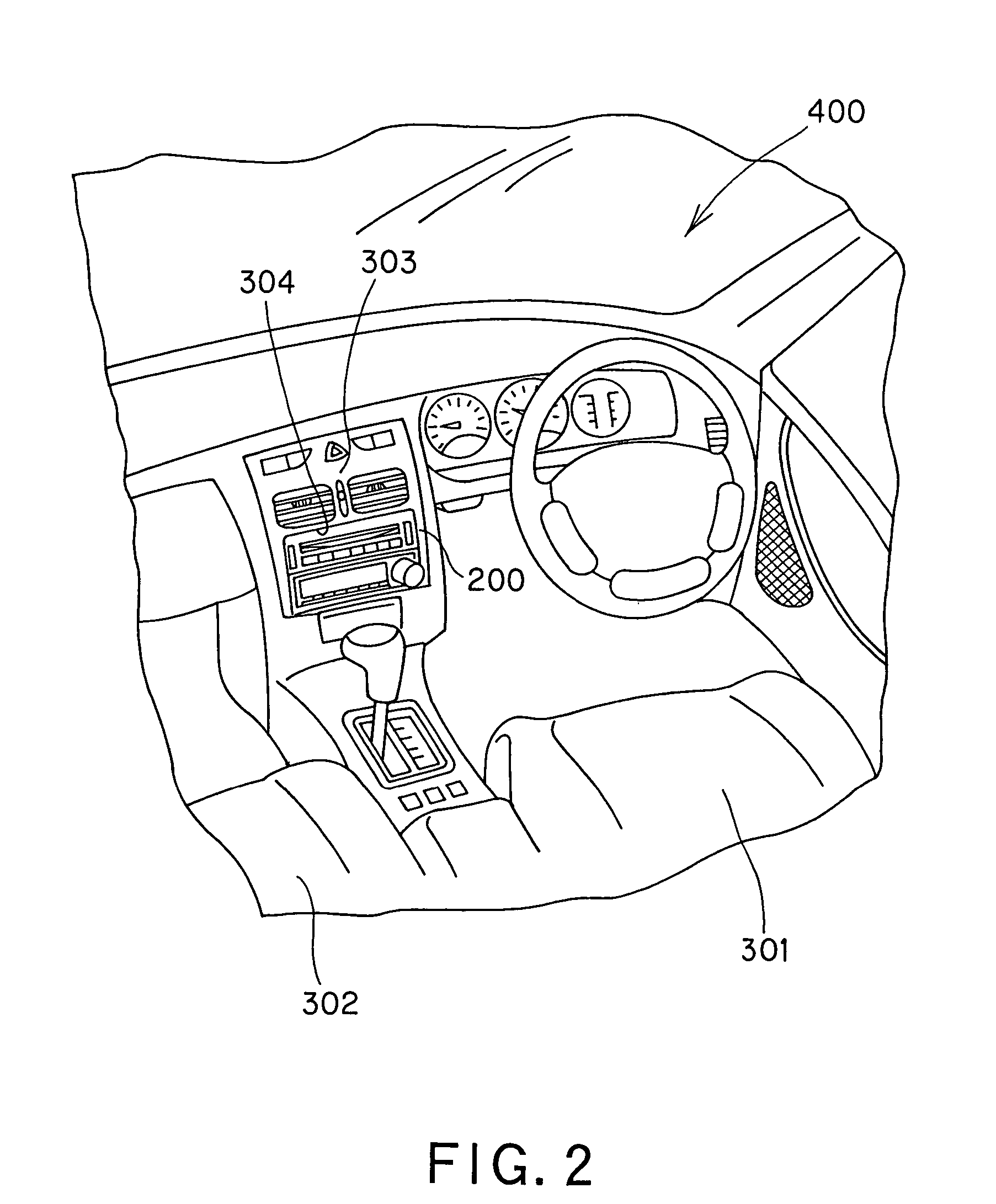
[0069]The in-vehicle player to which the present invention is applied is, for example, a small-size disc changer 200 set in a dashboard (or called a console panel or center panel) 303 provided in front of a driver's seat 301 and a navigator's seat 302 between these seats in a passenger room 300 as shown in FIG. 2.

[0070]In the disc changer 200, as shown in FIG. 3, six compact discs (CD hereinafter referred to simply as discs) 2 can be contained together in a device body 1 designed to fit a definite standard dimensions called a 1DIN size. An arbitrary one can be selected and played back among the discs 2 contained. Accordingly, discs 2 can be exchanged inside the passenger room 300 thus to provide improved conveniences.

[0071]Meanwhile, the dashboard 303 is provided with a mount space 304 having dimensions according to a definite standard such as 1DIN or ...


PUM

PropertyMeasurementUnit
frequenciesaaaaaaaaaa
loss coefficient tan δaaaaaaaaaa

Abstract

An in-vehicle player which is mounted in a dashboard in a passenger room of a vehicle comprises: an outer housing to be assembled in a mount space provided in the dashboard; a device body contained in the outer housing; and a cushion member interposed between the outer housing and two side surfaces of the device body, wherein the cushion member is made of viscous elastic material, the cushion member has an end surface which is substantially parallel to a shearing direction thereof and stuck to a mount surface of the device body by viscosity thereof, and the cushion member has another end surface which is substantially parallel to the shearing direction and stuck to a mount surface of the outer housing by viscosity thereof, thereby to attach the cushion member to be elastically deformable in the shearing direction between the outer housing and the two side surfaces of the device body.

Description

CROSS REFERENCES TO RELATED APPLICATIONS[0001]The present invention contains subject matter related to Japanese Patent Application JP 2004-122209 filed in the Japanese Patent Office on Apr. 16, 2004, the entire contents of which being incorporated herein by reference.BACKGROUND OF THE INVENTION[0002]1. Field of the Invention[0003]The present invention relates to an in-vehicle player set on a dashboard in a vehicle compartment.[0004]2. Description of Related Art[0005]For example, car audio systems and car navigation systems have been being widely spreading as in-vehicle players which plays back music and information such as audio and images. These in-vehicle players work to play back information recorded on disc-type recording media such as compact discs (CD), digital versatile discs (DVD), mini discs (MD), or tape-type recording media such as cassette tapes. In recent years, in-vehicle players capable of recording information into hard disc drives (HDD) or exchanging information via...

Claims


Application Information

Patent Timeline
Patent Type & Authority Patents(United States)
IPC IPC(8): G11B33/08B60R11/00B60R11/02F16D1/072F16F7/00F16F15/04F16F15/08G11B17/22G11B23/08H02K15/00
CPCB60R11/0211G11B33/08G11B17/223B60R2011/0005
Inventor KUMEDA, KAZUYUKITAKA, YOSHITERUTAKIZAWA, KAZUYUKITAKAHASHI, HISAOIWABUCHI, NORIOMATSUSHITA, TAKUSHI
Owner SONY CORP
Learn More