Pressure and current reducing impeller

a technology of impeller and pressure reduction, applied in the direction of machines/engines, mechanical equipment, liquid fuel engines, etc., can solve problems such as pressure loss, achieve the effects of reducing pressure, improving overall pump efficiency, and suitability for operation

Inactive Publication Date: 2008-09-16
BORGWARNER INC
View PDF22 Cites 5 Cited by
  • Summary
  • Abstract
  • Description
  • Claims
  • Application Information

AI Technical Summary

Benefits of technology

[0005]The present invention relates a secondary air system having a regeneration air pump wherein the vanes of the impeller are tapered from a point along the length of the vane to the base of the vane inside the air pump. The tapered vanes create desirable flow characteristics. The impeller arrangement provides an ideal flow characteristic that prevents high pressure from restricting the movement of the downstream valve. Thus, the tapered vanes create a non-linear flow versus pressure characteristic. This non-linear characteristic created by the tapered vanes allows the secondary air system to maintain suitable operation at lower flow and pressure levels. In addition, the tapered vanes of the impeller fan also function as a relief feature which creates a pressure loss as pressure builds in the system. Since the pressure in the secondary air system is reduced, a lower pressure is obtained at a dead head condition. The impeller arrangement also improves overall pump efficiency. All in all the invention described herein provides a secondary air system where the dead head pressure characteristics created in the secondary air system will be lower than the standard dead head pressure so that the valve can function properly, out of the range of undesirable back pressures and high currents.

Problems solved by technology

In addition, the tapered vanes of the impeller fan also function as a relief feature which creates a pressure loss as pressure builds in the system.

Method used


Image

  • Pressure and current reducing impeller
  • Pressure and current reducing impeller
  • Pressure and current reducing impeller

Examples


Embodiment Construction

[0014]The following description of the preferred embodiment(s) is merely exemplary in nature and is in no way intended to limit the invention, its application, or uses.

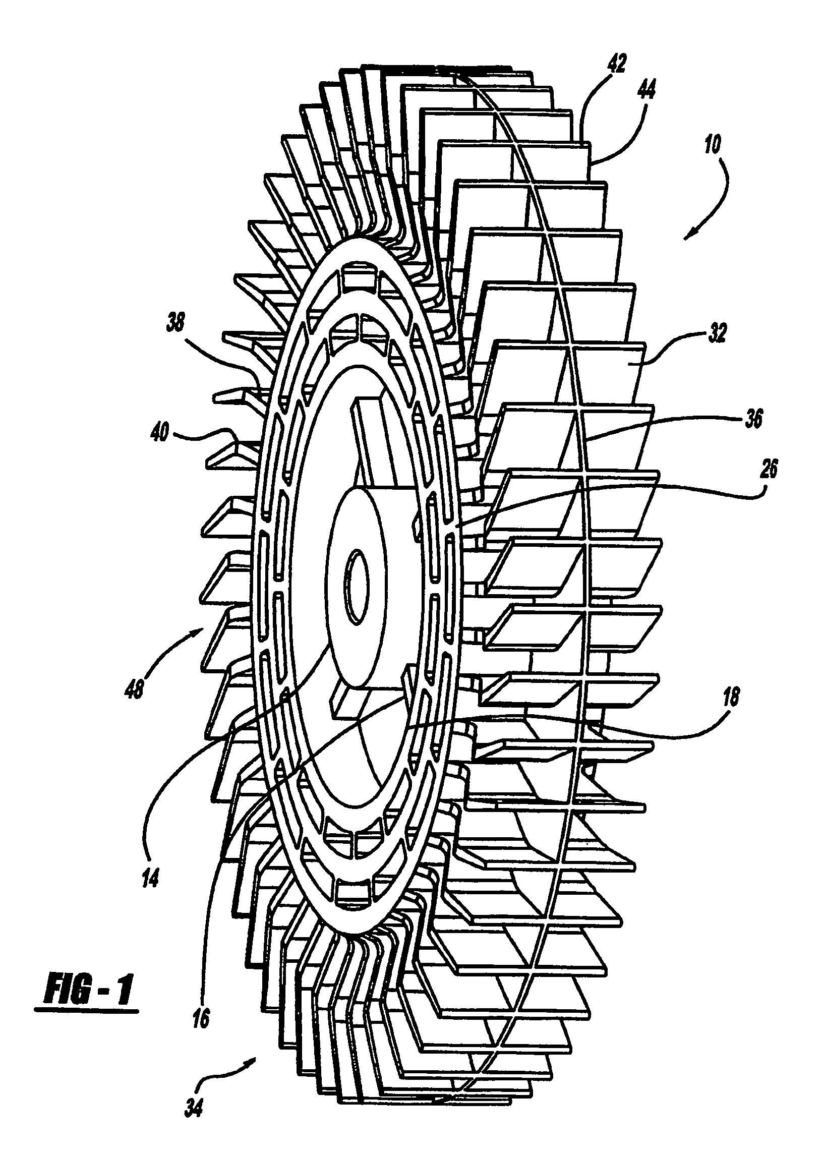
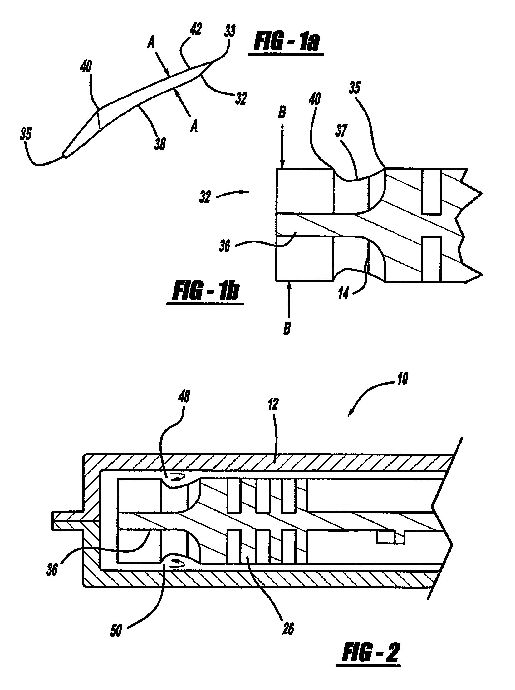
[0015]Referring to FIGS. 1, 1a, 1b, and 2, an impeller fan is generally shown at 10 and the impeller 10 has a casing 12. The casing 12 has an inlet (not shown) and an outlet (not shown), in which the air flows in and out of the casing 12 respectfully. The center of the impeller 10 has an inner radial surface 14 that creates an axial bore where a shaft (not shown) can extend through the axial bore. The impeller 10 can then rotate. The impeller 10 has at least one radial support 16 that is spaced circumferentially around the inner radial surface 14, and extends radially to an outer radial surface 18. Therefore, the radial supports 16 connect the inner radial surface 14 with the outer radial surface 18.

[0016]Vanes 32 are spaced circumferentially around the impeller frame 26. The spacing of the vanes 32 around the outer r...


PUM


Abstract

A secondary air system providing a regeneration air pump wherein the vanes of the impeller are tapered from a point along the length of the vane to the root of the vane inside the air pump. The tapered vanes create desirable flow characteristics. The tapered vanes create a non-linear flow versus pressure characteristic. Thus, the tapered vanes in combination with a divider that extends circumferentially around the impeller and through the vanes causes the flow to increase. This non-linear characteristic created by the tapered vanes allows the secondary air system to maintain suitable operation at lower flow and pressure levels. Due to the tapered feature on the impeller, a dead head pressure is obtained at a lower pressure. The impeller arrangement also provides overall pump efficiency improvements.

Description

FIELD OF THE INVENTION[0001]The present invention relates to a secondary air fan used in an exhaust system for a motor vehicle.BACKGROUND OF THE INVENTION[0002]When an engine goes through a cold start condition a secondary air flow fan can be used to inject air into the engine's exhaust system. The reason the air is injected into the exhaust system is so that oxygen is present in the exhaust system and causes excess hydrocarbons to be combusted. This also helps the catalytic converter to perform efficiently or achieve optimal temperature in a shorter amount of time.[0003]An impeller fan can be used to create the air movement in the secondary air flow system. One phenomena that can occur with secondary air flow systems is what is referred to as “dead head” condition. A dead head condition is when the air flow or output channel from the impeller becomes blocked. In other words, due to impeller design the pump will reach relatively high pressures at dead head and prevent the downstream...

Claims


Application Information

Patent Timeline
Patent Type & Authority Patents(United States)
IPC IPC(8): F04D5/00
CPCF04D29/188F04D29/18
Inventor PETERSON, TODDADHVARYU, KETANJARAMILLO, RAMON
Owner BORGWARNER INC
Why Eureka
Try Eureka