
Body-supporting device

a support device and body technology, applied in the field of chairs, can solve the problems of difficult heat accumulation under the users' hips and behind the users' backs, exerting a lot of considerable pressure on users' hips and backs,

Inactive Publication Date: 2008-09-16
LIN PETER
View PDF8 Cites 107 Cited by
  • Summary
  • Abstract
  • Description
  • Claims
  • Application Information

AI Technical Summary

Benefits of technology

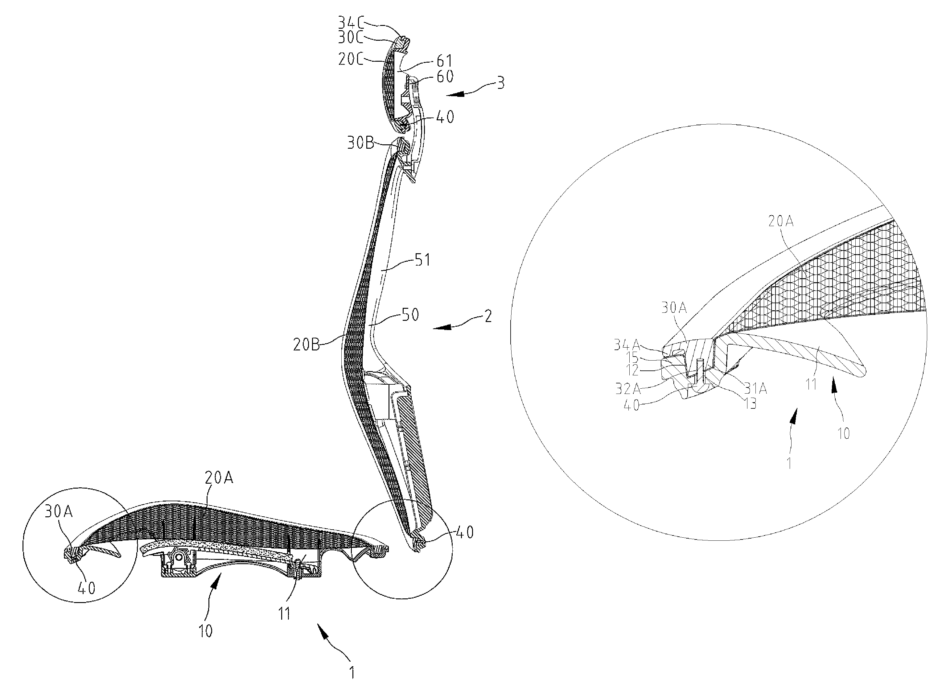
[0008]According to the present invention, a body-supporting device includes a tray, a net and a frame. The tray includes a margin and a groove in the margin. The groove gets narrower downwardly. The net includes a margin. The frame includes a first rib for inserting the margin of the net into the groove of the tray and a second rib for pressing the margin of the net against the margin of the tray. The first rib gets narrower downwardly. Fasteners are driven into the first rib of the frame through the margin of the tray. The sandwiching of the margin of the net between the first rib of the frame and the margin of the tray gets firmer as the fasteners get tighter in the first rib of the frame.
[0009]An advantage of the body-supporting device of the present invention is firm sandwiching of the margin of the net between the frame and the margin of the tray.
[0011]Still another advantage of the body-supporting device of the present invention is easy preparation of the net.
[0012]Still another advantage of the body-supporting device of the present invention is easy assembly.
[0013]Still another advantage of the body-supporting device of the present invention is a low cost.

Problems solved by technology

However, conventional chairs exert a lot of considerable pressure on users' hips and backs and cause heat to accumulate beneath the users' hips and behind the users' backs.
This is, however, difficult since the nets define meshes.
It is, however, difficult and costly to make the tubular portions 61 of the net 6 by adhesion.
This entails high costs in preparing and storing the parts of the chairs.

Method used


Image

  • Body-supporting device
  • Body-supporting device
  • Body-supporting device

Examples


Embodiment Construction

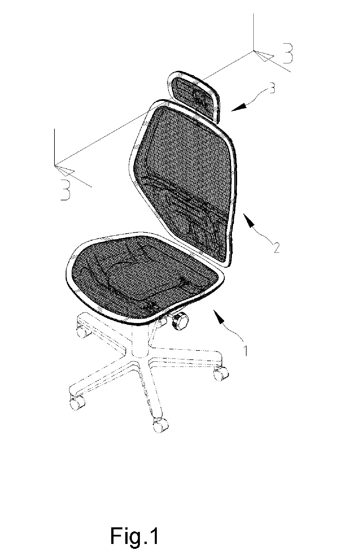
[0021]Referring to FIG. 1, a chair includes a seat 1, a backrest 2 and a headrest 3 according to the preferred embodiment of the present invention. Each of the seat 1, the backrest 2 and the headrest 3 can be referred to as the “body-supporting device.”

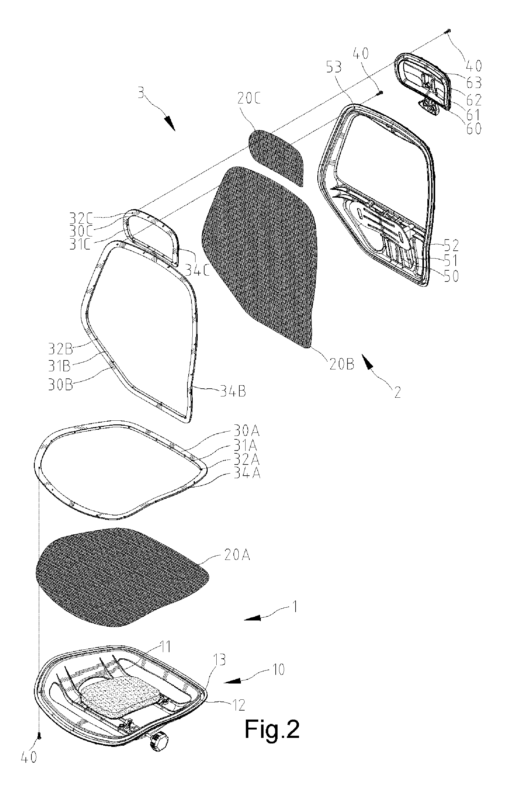
[0022]The seat 1 includes a tray 10, a net 20A and a frame 30A. The tray 10 defines a space 111 in the center, a groove 12 around the space 111 and apertures 13 in communication with the groove 12. The groove 12 gets narrower downwardly.

[0023]The net 20A is cut according to the tray 10. The area of the net 20A is intended to be larger than an area defined by the tray 10.

[0024]The frame 30A is made according to the groove 12. The frame 30A includes a first rib 31A and a second rib 34A both on the bottom. The first rib 31A gets narrower downwardly. Screw holes 32A are defined in the rib 31A of the frame 30A.

[0025]Referring to FIG. 3, the first rib 31A of the frame 30A and a first portion of the margin of the net 20A are inserted into th...


PUM


Abstract

A body-supporting device includes a tray, a net and a frame. The tray includes a margin and a groove in the margin. The groove gets narrower downwardly. The net includes a margin. The frame includes a first rib for inserting the margin of the net into the groove of the tray and a second rib for pressing the margin of the net against the margin of the tray. The first rib gets narrower downwardly. Fasteners are driven into the first rib of the frame through the margin of the tray. The sandwiching of the margin of the net between the first rib of the frame and the margin of the tray gets firmer as the fasteners get tighter in the first rib of the frame.

Description

BACKGROUND OF INVENTION[0001]1. Field of Invention[0002]The present invention relates to a chair and, more particularly, to a body-supporting device such as a seat, a backrest and a headrest for use in a chair.[0003]2. Related Prior Art[0004]Chairs are important for people and more so for those who spend most of their time sitting and working. Manufacturers have been trying to come up with comfortable chairs. However, conventional chairs exert a lot of considerable pressure on users' hips and backs and cause heat to accumulate beneath the users' hips and behind the users' backs.[0005]Nets have been used in seats, backrests and headrests. The nets exert proper pressure on the users' hips and backs and allow heat to disperse from the users' hips and backs. Conventionally, screws are used to connect the nets to tray-like elements of the seats, backrests and headrests. This is, however, difficult since the nets define meshes.[0006]According to Taiwanese Patent M262101, a net 6 is provid...

Claims


Application Information

Patent Timeline
Patent Type & Authority Patents(United States)
IPC IPC(8): A47C7/02
CPCA47C31/023A47C7/282
Inventor LIN, PETER
Owner LIN PETER
Learn More