
Weigh in motion technology

a technology of motion and weight, applied in the field of weight measurement apparatus and methods, can solve the problems of significant limitations and shortcomings of the background technology

Active Publication Date: 2008-09-09
INTERCOMP
View PDF14 Cites 25 Cited by
  • Summary
  • Abstract
  • Description
  • Claims
  • Application Information

AI Technical Summary

Benefits of technology

[0010]The present invention provides a weighing system, scale apparatus and load cells, and methods of making and using the system, scale and load cells which are practical, reliable, accurate and efficient, and which is believed to fulfil a need and to constitute an improvement over the background technology.

Problems solved by technology

The background technology is believed to have significant limitations and shortcomings.

Method used


Image

  • Weigh in motion technology
  • Weigh in motion technology
  • Weigh in motion technology

Examples


Embodiment Construction

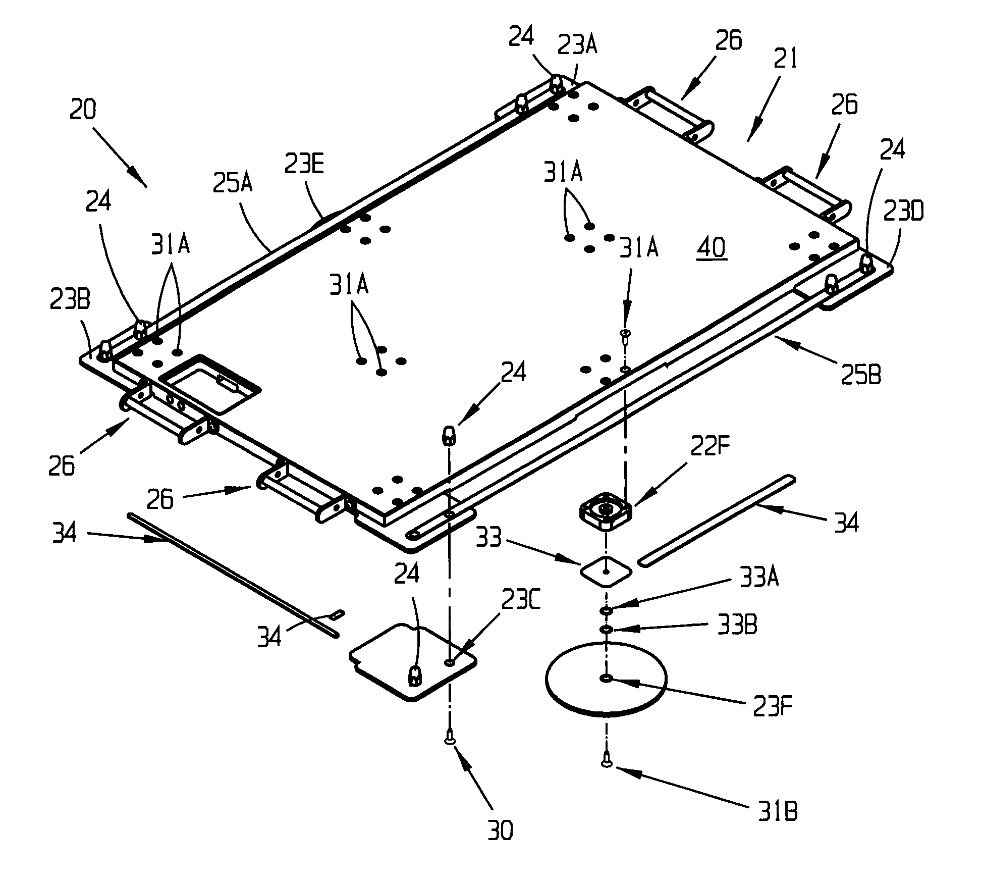
[0083]FIGS. 1-45, show embodiments of systems, apparatus, articles, assemblies, mechanisms, circuitry and processes of the present invention. The embodiments described are intended to be illustrative and not to be exhaustive or limit the invention to the exact forms disclosed. The embodiments are chosen and described so that persons skilled in the art will be able to understand the invention and the manner and process of making and using it.

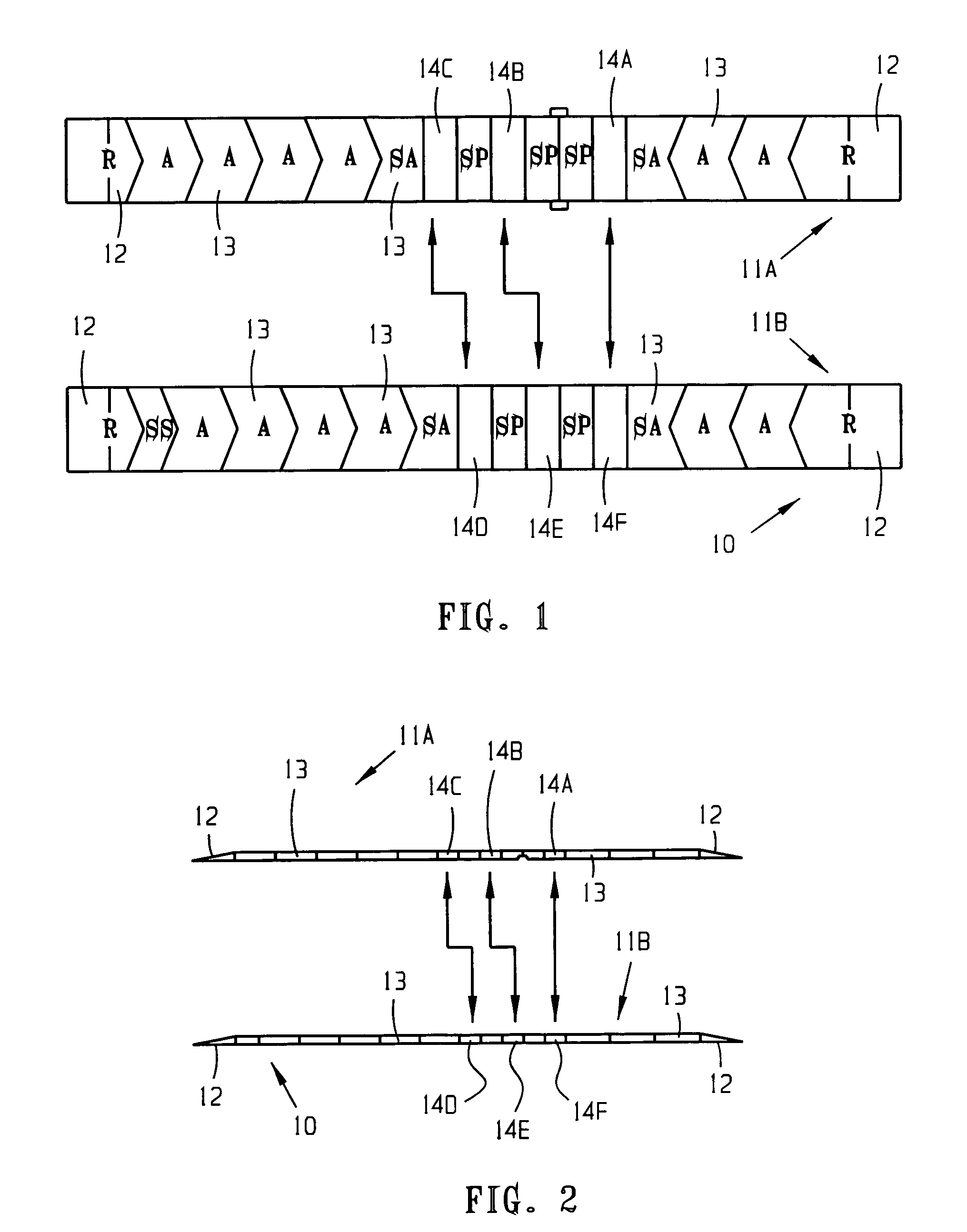
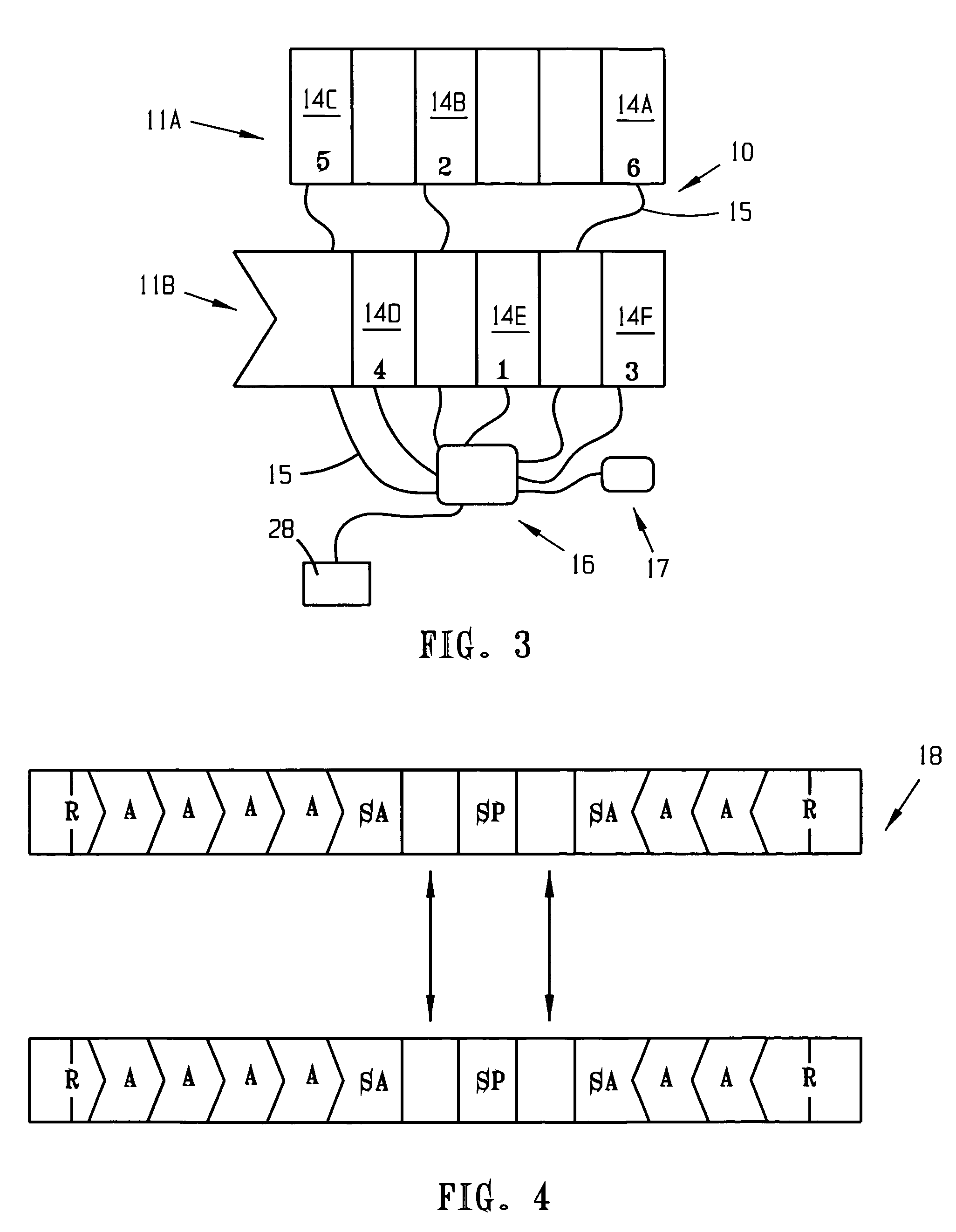
[0084]Referring to FIGS. 1-3 an embodiment of the weighing system 10 is useable to weigh vehicles, vehicle contents or other material, while in motion with respect to the system 10. The system 10 is portable, relatively light weight, and simple to install, break down, move and store. The system 10 includes a pair of wheel platforms or courses 11a and b of components which are aligned to correspond to the tires or treads of a vehicle (not shown) being weighed. Each course 11 includes a plurality of scales 14 preferably connected to approach member...


PUM


Abstract

A weighing system has at least one weighing platform receiving a moving load to be weighed, the platform includes at least one scale member connected to at least two approach members, and including at least one ramp member connected to at least one of the approach members. An interface is communicatively connected to the scale member. A controller is connected to the interface. And, a power supply is connected to the interface. Also disclosed is a weighing scale having a rigid pad having a top surface for receiving the load and a bottom surface. A plurality of load cells are included, each having at least two top surfaces and at least two bottom surfaces. A top surface of each load cell is connected at a predetermined location to the bottom surface of the pad. A foot member contacts the ground and is connected to a bottom surface of the load cell. Further disclosed is a load cell having a body defined by first and second sides. The body has a peripheral region of a predetermined thickness and a central region of a predetermined thickness which is less than that of the peripheral region. The central region is inset on each side with respect to the peripheral region. The central region is adapted for contact with a force.

Description

CROSS-REFERENCE TO RELATED APPLICATIONS, IF ANY[0001]This application claims the benefit under 35 U.S.C. § 119(e) of co-pending U.S. Provisional Patent Application Ser. No. 60 / 626,140, filed Nov. 9, 2004, which is hereby incorporated by reference.37C.F.R. §1.71(e) AUTHORIZATION[0002]A portion of the disclosure of this patent document contains material which is subject to copyright protection. The copyright owner has no objection to the facsimile reproduction by anyone of the patent document or the patent disclosure, as it appears in the US Patent and Trademark Office patent file or records, but otherwise reserves all copyright rights whatsoever.STATEMENT REGARDING FEDERALLY SPONSORED RESEARCH OR DEVELOPMENT[0003]Not applicable.REFERENCE TO A MICROFICHE APPENDIX, IF ANY[0004]Not applicable.BACKGROUND[0005]1. Field of the Invention[0006]The present invention relates, generally, to weight measurement apparatus and methods. Particularly, the invention relates to an apparatus and method ...

Claims


Application Information

Patent Timeline
IPC IPC(8): G01G19/02
CPCG01G21/22G01G19/035
Inventor KROLL, WILLIAM P.EVENSON, RANDIEYOUNG, MATHEW C.WISSINK, JASON
Owner INTERCOMP
Learn More