
Precise frequency generation for low duty cycle transceivers using a single crystal oscillator

a technology of crystal oscillator and low-duty cycle transceiver, which is applied in the direction of pulse automatic control, substation equipment, and multi-antenna systems. it can solve the problems of not being able to use battery-powered reduced function devices, consuming 400 to 800 micro amps by itself, and unable to achieve precise frequency generation

Active Publication Date: 2008-09-02
SILICON LAB INC
View PDF10 Cites 74 Cited by
  • Summary
  • Abstract
  • Description
  • Claims
  • Application Information

AI Technical Summary

Benefits of technology

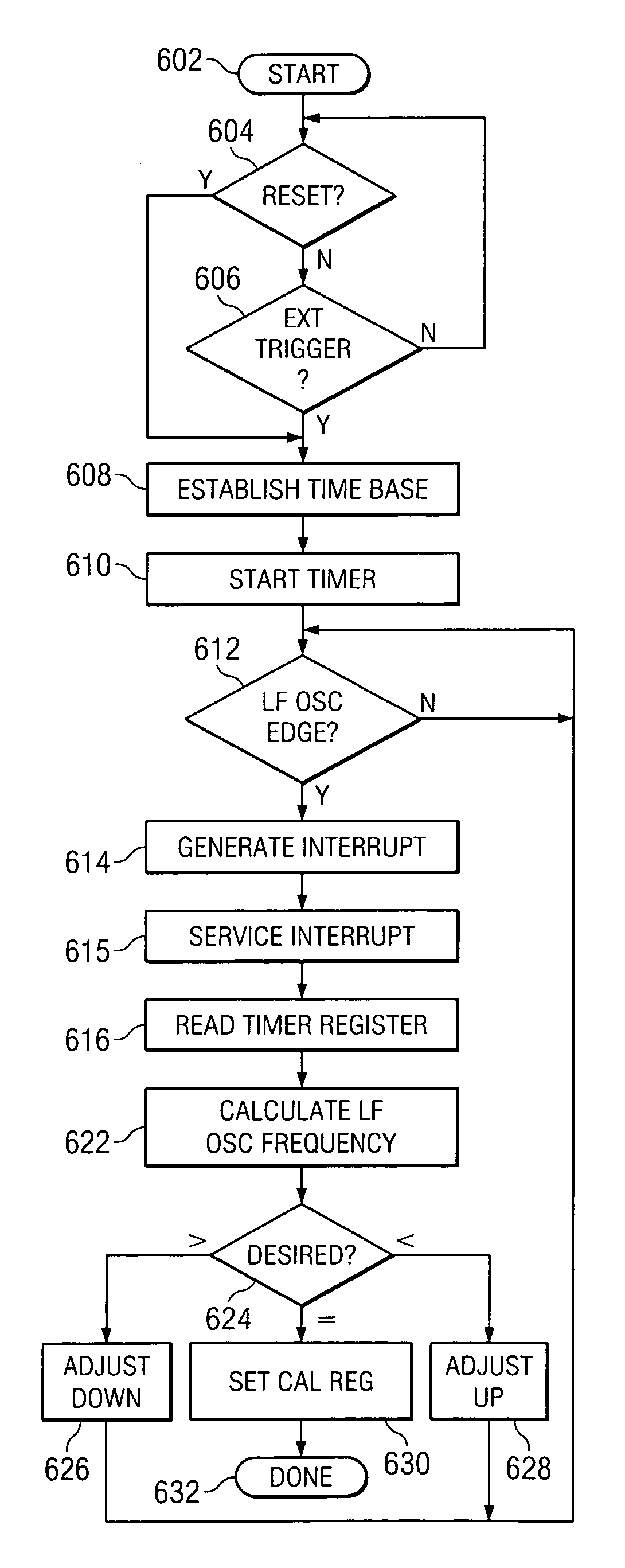
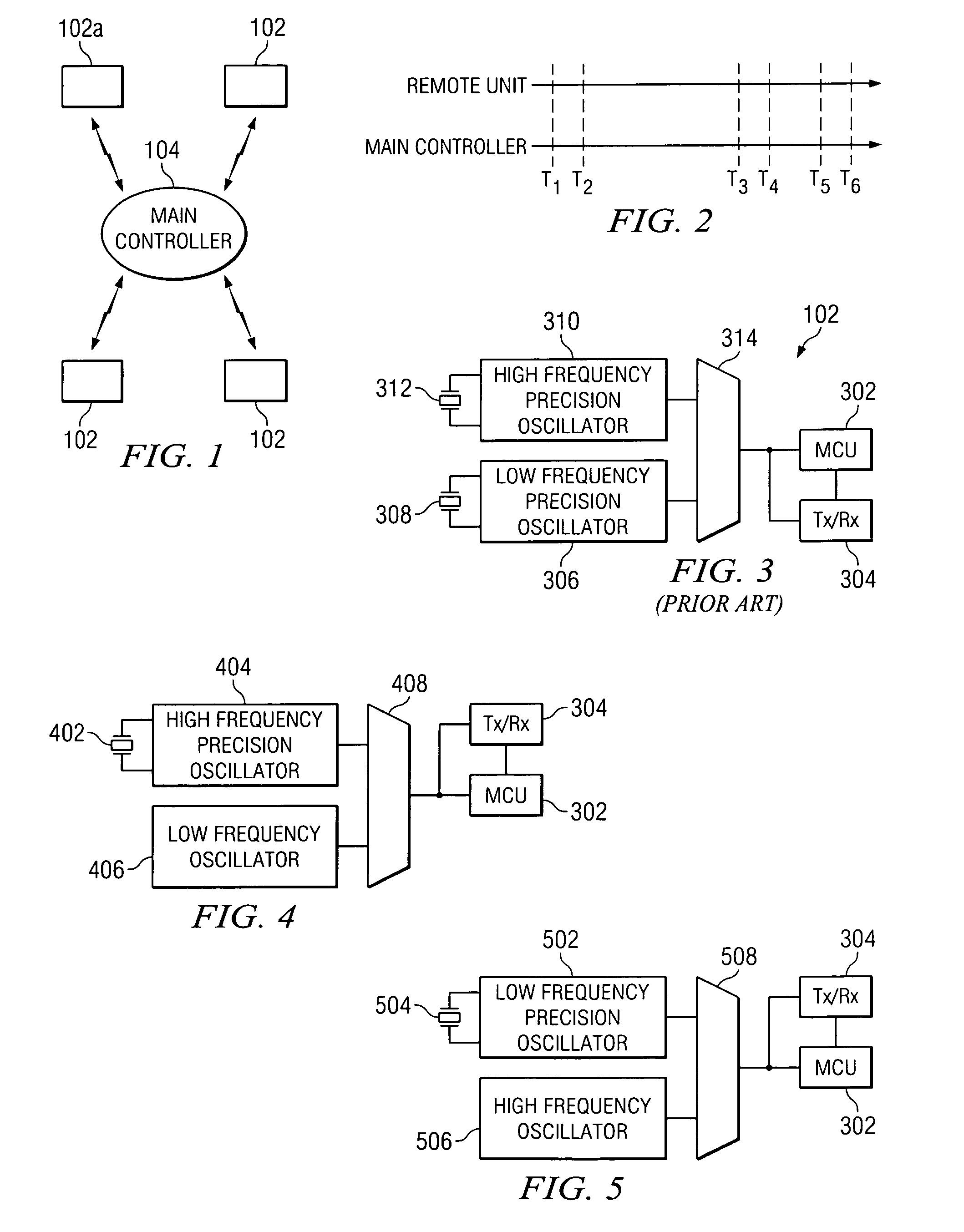
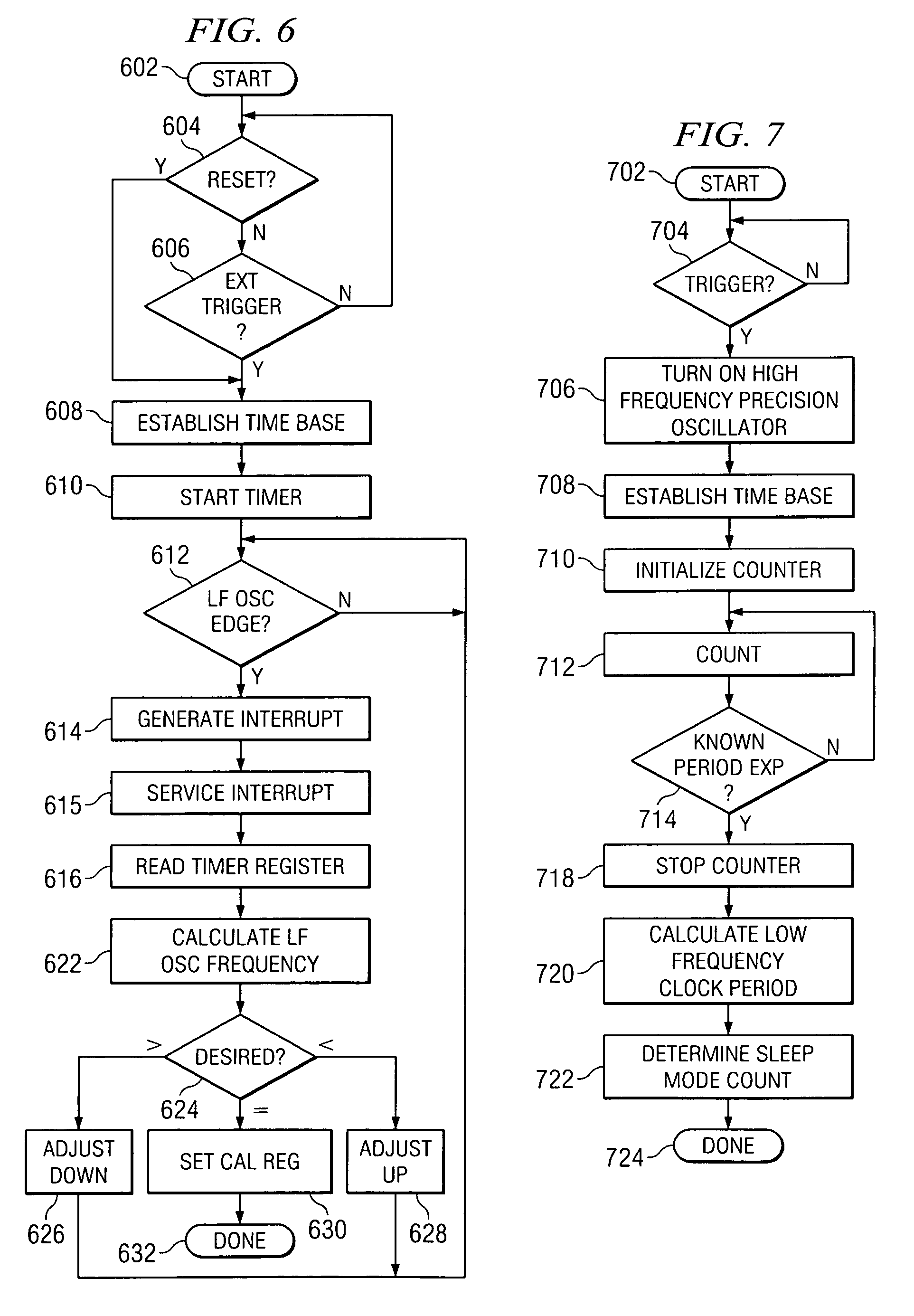
The present invention is about a device and method for calibrating a non-crystal oscillator in a remote unit using a crystal oscillator. The device creates a time base based on the oscillations of the crystal oscillator and compares the number of oscillations of the non-crystal oscillator with the known time period. An adjustment is determined based on the time base and the compared number of oscillations. The control of the remote unit is then adjusted based on this adjustment. The technical effect of this invention is to improve the accuracy and reliability of the non-crystal oscillator in the remote unit.

Problems solved by technology

This crystal oscillator typically consumes 400 to 800 micro amps by itself which is far too much current for the requirements of a sleep mode.
In a reduced function device, there is a trade off in the tolerance of the RTC versus power consumption, since an inaccurate RTC will require the device to come out of sleep mode sooner so that it can be guaranteed to receive the beacon from the network coordinator.
However, as noted earlier, this is not an option for battery-powered reduced function devices because a 16 MHz crystal oscillator typically consumes more than 100 times as much current as a 32.768 KHz crystal oscillator.
These battery powered devices thus generally require both crystal oscillators, adding considerably to the cost and physical size of the transceiver.
It should be pointed out that it is possible to build oscillators that do not employ a crystal as the frequency-determining element, but they do not have accuracy sufficient to meet the requirements of 802.15.4 or similar systems.

Method used


Image

  • Precise frequency generation for low duty cycle transceivers using a single crystal oscillator
  • Precise frequency generation for low duty cycle transceivers using a single crystal oscillator
  • Precise frequency generation for low duty cycle transceivers using a single crystal oscillator

Examples


Embodiment Construction

[0022]Referring now to the drawings, and more particularly to FIG. 1, there is illustrated a network operating according to, for example, the 802.15.4 protocol or other short range wireless communications protocol wherein a plurality of remote transceiver units 102 are in wireless communication with a main controller 104 using a short range wireless protocol. In order to enable communication between the remote transceiver units 102 and the main controller 104 while maintaining battery power at the remote transceiver units 102, an assigned slot communication protocol must be utilized. Thus, as illustrated in FIG. 2, the remote transceiver units 102 and the main controller unit 104 have an initial communication period where they are in communication with each other from time t1 to time t2. Remote transceiver unit 102a and the main controller unit 104 each know that this is the time period for the remote transceiver unit 102a to communicate with the main controller unit 104. During thi...


PUM


Abstract

An apparatus and method for calibrating a non-crystal oscillator in a transceiver unit using a crystal-oscillator includes the step of establishing a time base based upon oscillations of the crystal oscillator. A comparison of the number of oscillations for the non-crystal oscillator and the crystal oscillator is made during a known time period is made. An adjustment is determined based upon the established time base and the compared number of oscillations. The transceiving of the transceiver unit is then controlled based upon this adjustment.

Description

CROSS-REFERENCE TO RELATED APPLICATIONS[0001]This application is related to U.S. patent application Ser. No. 10 / 865,110 filed on Jun. 10, 2004 and entitled “Method and Apparatus for Calibration of a Two Frequency Oscillator in a Processor-Based System,” which is incorporated herein by reference.TECHNICAL FIELD OF THE INVENTION[0002]The present invention relates to the synchronization of an oscillator for low duty cycle transceivers, and more particularly, to the synchronization of an oscillator for a low duty cycle transceiver using a single crystal oscillator.BACKGROUND OF THE INVENTION[0003]The IEEE 802.15.4 Standard provides a radio data transceiver protocol that is optimized for low data rate, short range, low power and cost. The low power is partly a consequence of the low data rate and short range, but the standard also provides for varied low duty cycle modes in which the tranceivers will stay in a sleep state for most of the time, periodically waking up to communicate short ...

Claims


Application Information

Patent Timeline
Patent Type & Authority Patents(United States)
IPC IPC(8): H04B1/40
CPCH03L7/00H03L1/00
Inventor WESTWICK, ALAN L.HOLBERG, DOUGLAS R.
Owner SILICON LAB INC
Learn More