
Method and device for determining wheel force

a technology of force and wheel, applied in the direction of heat treatment apparatus, instruments, furnaces, etc., can solve the problem of not being able to get data on the force exerted by the wheel on the rolling vehicle wheel

Inactive Publication Date: 2008-08-26
SUMITOMO RUBBER IND LTD
View PDF26 Cites 7 Cited by
  • Summary
  • Abstract
  • Description
  • Claims
  • Application Information

AI Technical Summary

Benefits of technology

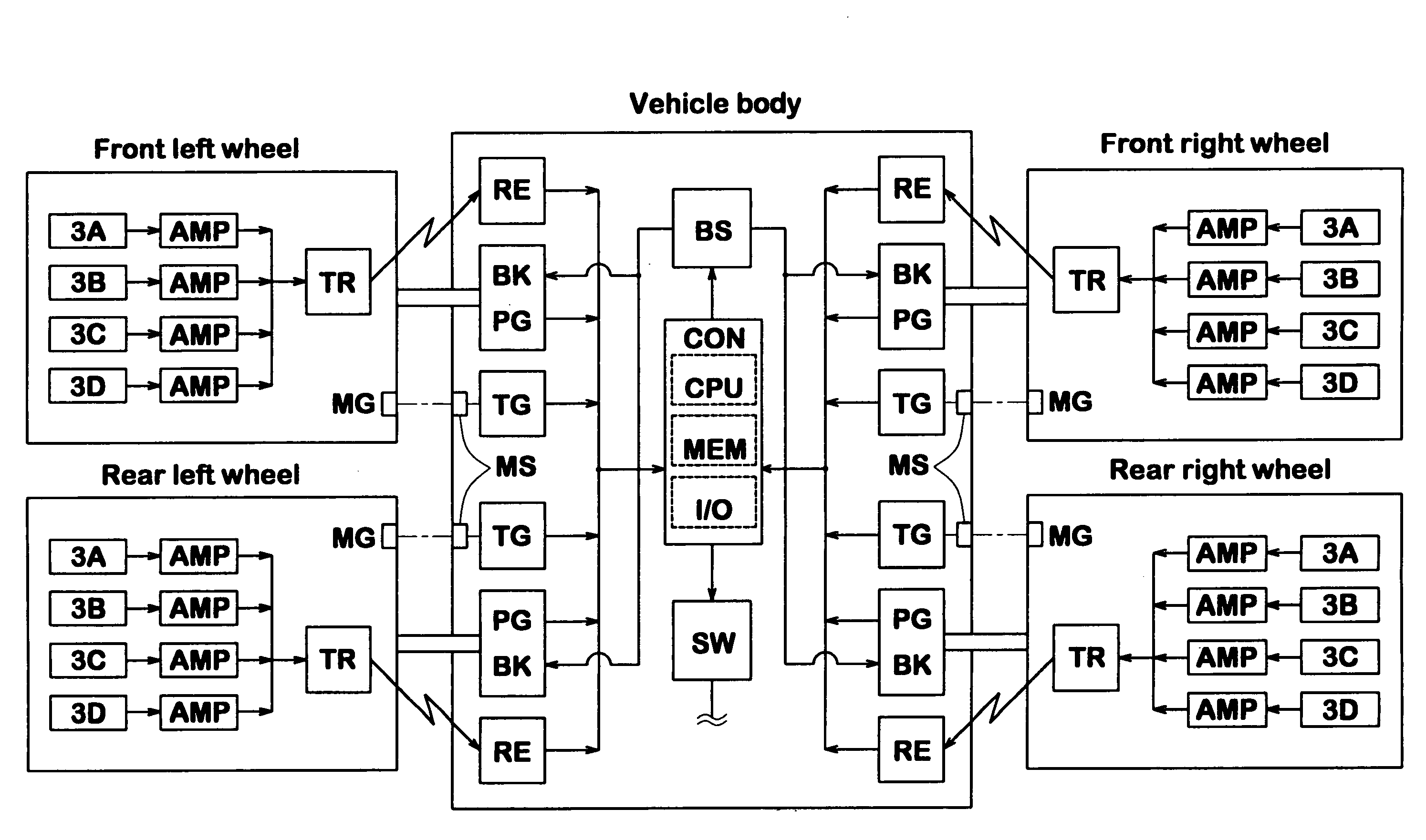
[0005]It is therefore, an object of the present invention to provide a method and device by which a force exerted on a vehicle wheel during running can be easily determined.

Problems solved by technology

Hitherto, however, there is no way to get data on the wheel forces exerted on rolling vehicle wheels during running.

Method used


Image

  • Method and device for determining wheel force
  • Method and device for determining wheel force
  • Method and device for determining wheel force

Examples


Embodiment Construction

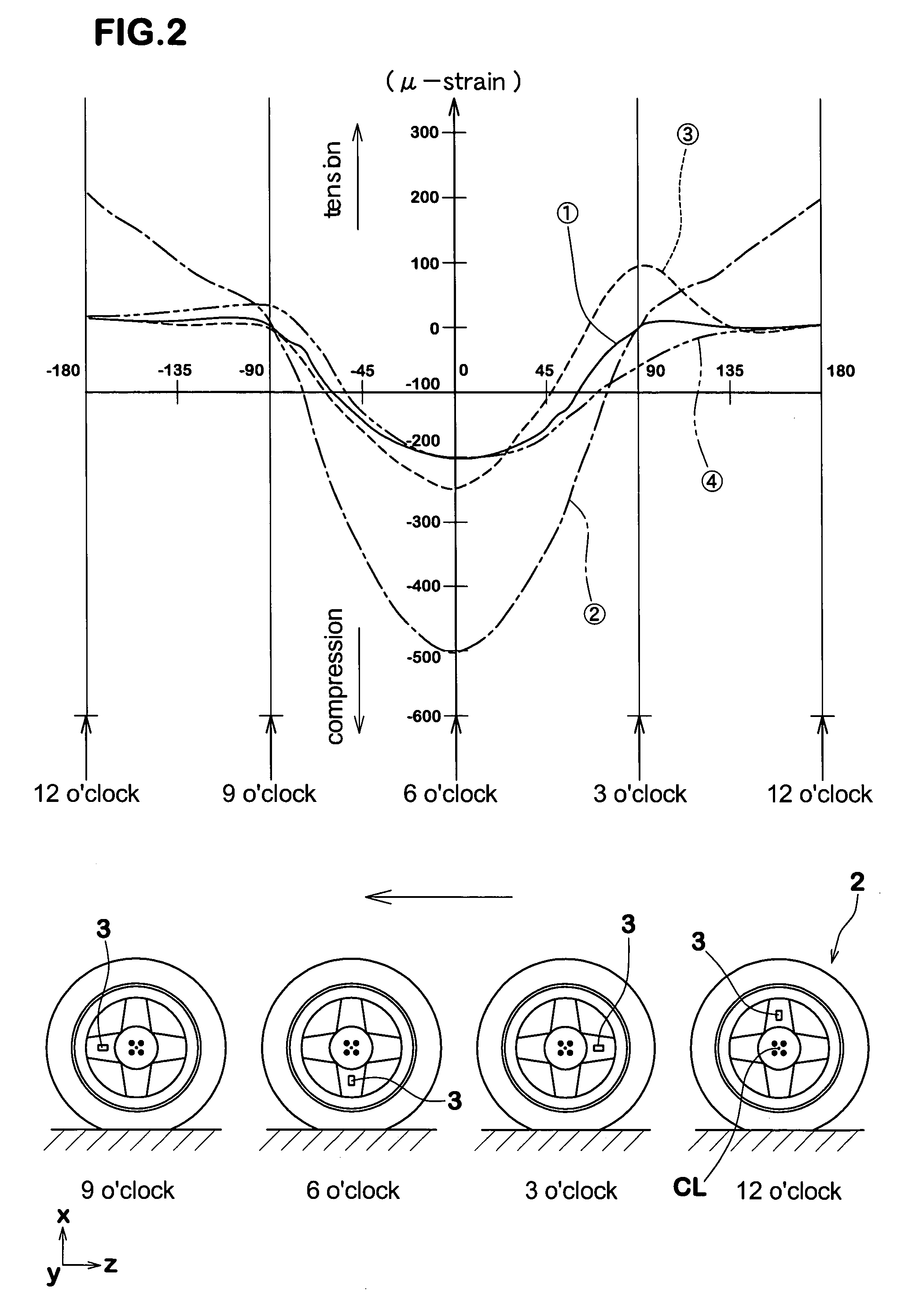
[0022]The gist of the present invention is to determine at least one kind of forces exerted on a vehicle wheel by utilizing a variation of a physical parameter of the rolling vehicle wheel itself.

[0023]Here, a vehicle wheel 2 comprises an radially outermost annular part 2a contacting with the road surface to cause friction against the road surface, and a radius part 2b2 extending radially outwardly from a hub attached to a vehicle axle towards the annular part 2a. In the case of an automobile, as shown in FIG. 1, a vehicle wheel 2 generally comprises a tire 2a and a wheel 2b. The tire 2a may be a pneumatic tire, a solid tire or the like. The wheel 2b comprises a rim 2b 1 on which the tire is mounted and a wheel disk 2b2 between the rim and a hub attached to a vehicle axle. The wheel disk 2b2 is the above-mentioned radius part, and thus it is meant for a disk-like relatively thin part and also radius rods, spokes and the like.

[0024]As to the physical parameter, a strain is used in th...


PUM

PropertyMeasurementUnit
Forceaaaaaaaaaa
Forceaaaaaaaaaa
Forceaaaaaaaaaa

Abstract

A method and device for determining force exerted on a rolling vehicle wheel. Firstly, data on a relationship between a force exerted on a vehicle wheel and a physical parameter such as strain of the radius part of the wheel at predetermined measuring positions are obtained. Using the obtained data on the relationship, a formula for the force is made. Then, the vehicle wheel is measured for the physical parameter during rolling, and using the measured physical parameter and formula, the force is calculated. The force may be a vertical force, lateral force, longitudinal force or self aligning torque. The physical parameter may be the magnitude of a radial strain.

Description

[0001]This Nonprovisional application claims priority under 35 U.S.C. § 119(a) on Patent Application No(s). 2002-352854 and 2003-127337 filed in Japan on Dec. 4, 2002 and May 2, 2003, respectively, the entire contents of which are hereby incorporated by reference.BACKGROUND OF THE INVENTION[0002]The present invention relates to a method and a device for determining wheel force exerted on a vehicle wheel during running.[0003]In recent years, the number of vehicles equipped with computer-aided control systems such as anti-lock brake system, attitude control system (suspension control system) and steer-by-wire system is rising.[0004]In such control systems, if data on the magnitude and direction of the wheel force exerted on a rolling vehicle wheel can be utilized, control accuracy will be dramatically improved. Hitherto, however, there is no way to get data on the wheel forces exerted on rolling vehicle wheels during running. In the car industry, therefore, there is a great demand for...

Claims


Application Information

Patent Timeline
IPC IPC(8): B60C23/06B60G17/0195B60T8/172C21D6/00C21D6/04C21D9/00G01L5/16G01L5/20G01M17/02
CPCB60G17/0195G01L5/20B60T8/1725C21D6/004C21D9/0068G01L5/161B60G2204/115B60G2400/64B60G2401/17B60G2401/172B60T2240/03B60W2420/22B60W2422/70C21D6/04C21D2211/008B60G2204/113G01L5/1627G01L5/162
Inventor SHIRAISHI, MASAKI
Owner SUMITOMO RUBBER IND LTD
Learn More