Eureka AIR delivers breakthrough ideas for toughest innovation challenges, trusted by R&D personnel around the world.

Optical device and virtual image display device

an optical device and virtual image technology, applied in the field of virtual image display devices, can solve the problems of difficult to combine or laminate interference fringes together, the diameter of the pupil cannot be increased, and the /b> cannot be increased, so as to improve the image resolution, eliminate or reduce monochromatic aberration, and improve the effect of image resolution

Active Publication Date: 2008-08-26
SONY CORP
View PDF9 Cites 277 Cited by
  • Summary
  • Abstract
  • Description
  • Claims
  • Application Information

AI Technical Summary

Benefits of technology

[0025]Accordingly, the present invention has an object to overcome the above-mentioned drawbacks of the related art by providing an optical device and virtual image viewing optical system in which the image resolution is increased by eliminating or reducing monochromatic aberration and diffraction chromatic aberration, light is diffracted with a higher efficiency by reducing the number of hologram elements used, color of display image is uniformized and pupil diameter is increased.
[0046]Therefore, the virtual image optical device according to the present invention can be designed more lightweight and compact, and can be produced with less costs. Also, in case this virtual image optical device is used as an HMD (Head Mounted Display), possible discomfort given to the user when it is mounted on the user's head can considerably be reduced.
[0047]Also, according to the present invention, diffraction can be made with an improved efficiency since only two reflection volume hologram gratings, first and second, are used. Further, since the reflection volume hologram grating is smaller in diffraction acceptance wavelength and larger in diffraction acceptance angle than the transmission volume hologram grating, so a display image can be uniformized in colors and the pupil diameter can be increased.
[0048]Further, since the first and second reflection volume hologram gratings used in the present invention do not act as any lens, so the monochromatic eccentric aberration can be eliminated. Also, since the diffraction acceptance wavelength is small and thus the diffraction chromatic aberration can be reduced, an image of a high resolution can be displayed on the viewer's pupil.
[0049]Moreover, according to the present invention, the interference fringe recorded on the first reflection volume hologram grating is equal in pitch on the hologram surface to that recorded on the second reflection volume hologram grating. Therefore, parallel rays of light incident at the same wavelength and incident angle can be prevented from being diffracted and reflected at different angles of diffraction and a virtual image of a high resolution can be displayed on the viewer's pupil.
[0050]Also, since the interference fringe recorded on each of the first and second reflection volume hologram gratings used in the present invention is a simple diffraction grating in which the interference fringe is simple, so the interference fringes can easily be combined together and the hologram layers each having the interference fringe recorded thereon can be laminated together. Thus, it is possible to diffract and reflect parallel pencil groups different in wavelength from each other, for example, RGB (R: Red light G: Green light; B: Blue light) as three primary colors of light, with an increased diffraction acceptance angle and without occurrence of diffraction chromatic aberration and reduction of color gamut.

Problems solved by technology

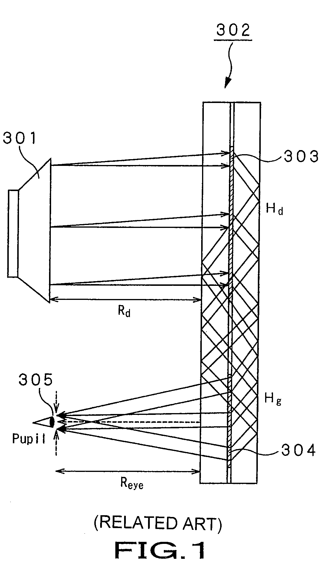
Firstly, in the virtual image viewing optical system shown in FIG. 1, divergent light projected from an image display device 301 is incident directly upon the transmission hologram lens 303 in the optical waveguide 302. When the distance between the image display device 301 and transmission hologram lens 303 is increased, namely, when the focal distance of the transmission hologram lens 303 is increased, for an increased magnification of the optical system, the diameter of the pupil 305 cannot be increased because the transmission hologram lens 303 has only a relatively small diffraction acceptance angle.
Secondly, since the interference fringe of the transmission hologram lens 303 has a complicated structure having a spherical phase component, it is difficult to combine or laminate the interference fringes together for a larger diffraction acceptance angle and the lens 303 cannot be designed to diffract light rays equal in wavelength and incident angle to each other with different efficiencies at the same diffraction angle.
Thirdly, in the virtual image viewing optical system shown in FIG. 1, since the transmission hologram lens 303 provided on the optical waveguide 302 diffracts image light rays coming from the image display device 301 while forming the light rays into a parallel pencil of rays, that is, while generating an optical power, a large monochromatic eccentric aberration will be caused, which will also lead to a reduced resolution of an image projected on the pupil.
Fourthly, the virtual image viewing optical system shown in FIG. 1 uses the transmission hologram grating 304 to correct achromatic aberration occurring in the transmission hologram lens 303. Since light rays incident upon the transmission hologram grating 304 is deflected only in the direction in the plane of the drawing in FIG. 1, aberration occurring in a direction perpendicular to at least the drawing plane cannot be canceled. The diffraction-caused chromatic aberration takes place because the two transmission holograms (transmission hologram lens 303 and transmission hologram grating 304) provided in the optical waveguide 302 are different from each other and there can be used substantially only a light source of which the waveband is narrow, which is a large constraint to this conventional virtual image viewing optical system.
If the two transmission holograms are identical transmission volume hologram gratings having no optical power, for example, another problem described below will take place.
However, in case the chromatic dispersion made by one of the holograms is larger, a pencil of rays traveling inside an optical waveguide will spread largely, resulting in a following problem.
When the largely spread pencil of rays having been diffracted by the first hologram and traveled inside the optical waveguide is diffracted at the second hologram and projected from the optical waveguide, it will spread largely in the traveling direction on the basis of its wavelength and lead to a deteriorated color uniformity of a virtual image on the viewer's pupil.
As above, in a hologram having a complicated interference patter, it is difficult to increase the diffraction acceptance of the interference fringe by laminating hologram layers together or combining the interference fringe.
Therefore, the pupil diameter cannot be increased.
Therefore, the conventional virtual image viewing optical system can neither use light with any improved efficiency nor enlarge the viewable range.

Method used


Image

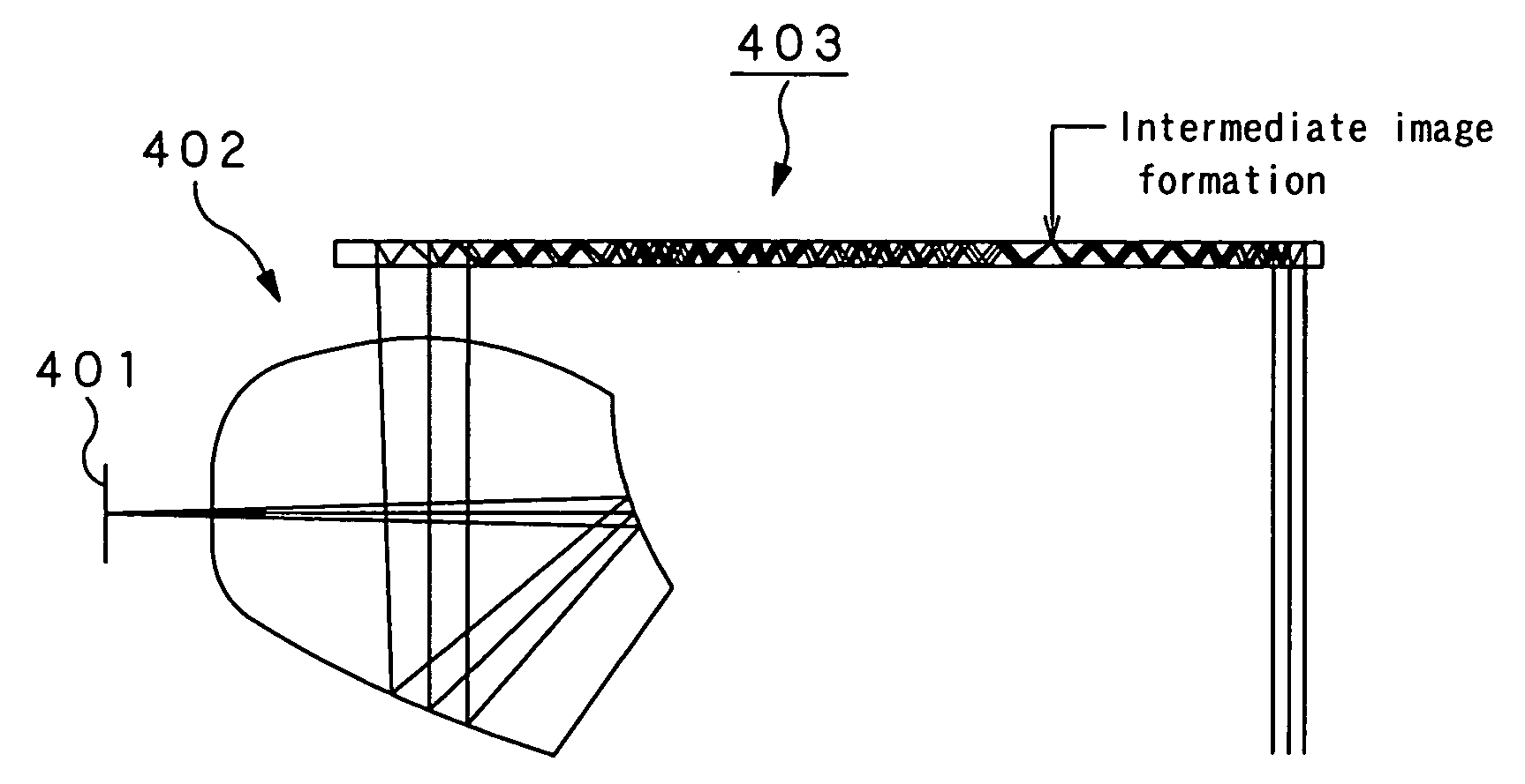
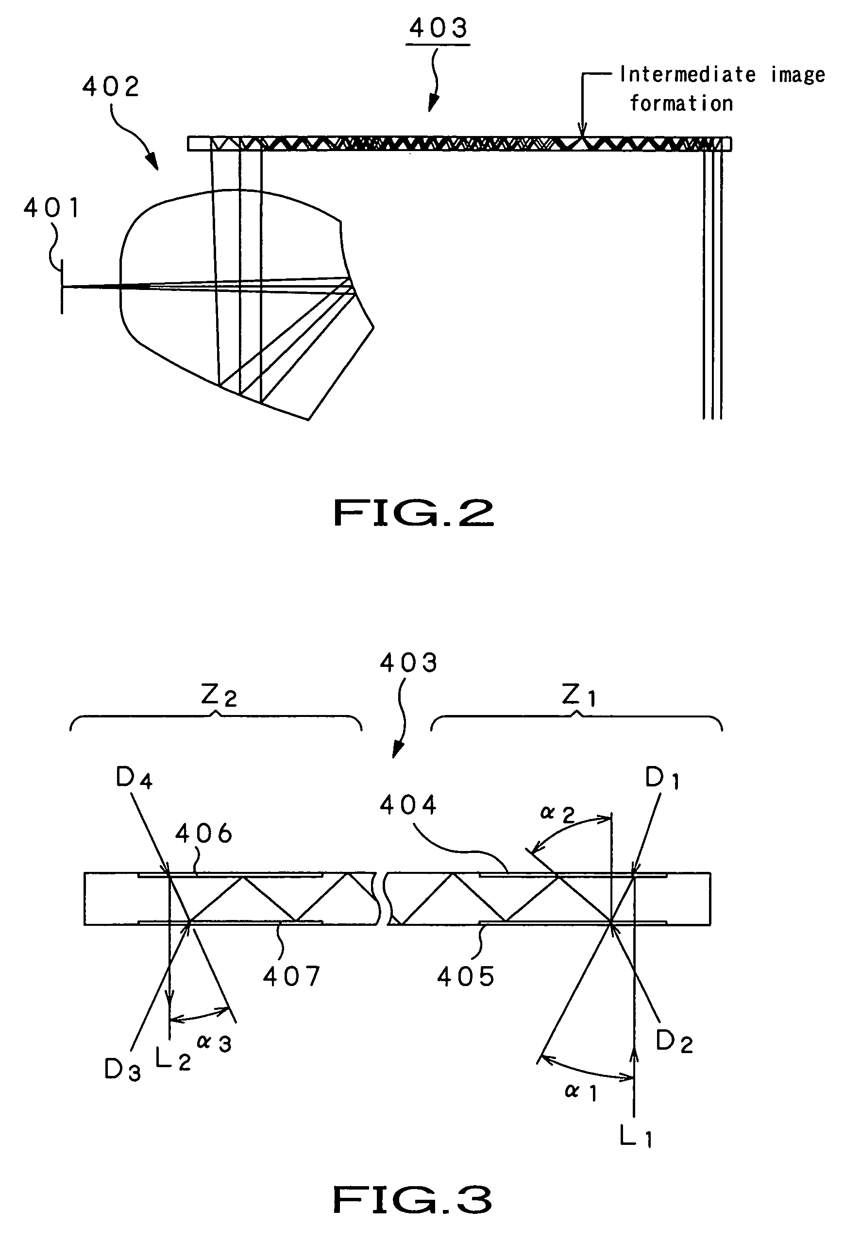
  • Optical device and virtual image display device
  • Optical device and virtual image display device
  • Optical device and virtual image display device

Examples


first embodiment

[0098]FIG. 8 shows a virtual image display device as a first embodiment of the present invention. The virtual image display device is generally indicated with a reference numeral 10. The virtual image display device 10 includes an image display element 11 to display an image, and a virtual image optical system to guide incident display light from the image display element 11 to a pupil 16 of the viewer.

[0099]The image display element 11 is for example an organic EL (Electro Luminescence) display, inorganic EL display, liquid crystal display (LCD) or the like.

[0100]The virtual image optical system includes a collimating optical system 12, optical waveguide 13, and a first reflection volume hologram grating 14 and second reflection volume hologram grating 15 provided on the optical waveguide 13.

[0101]The collimating optical system 12 receives an incident pencil from each pixel of the image display element 11 and forms the pencils into parallel pencil groups different in angle of field...

second embodiment

[0113]FIG. 11 shows a virtual image display device as a second embodiment of the present invention. The virtual image display device is generally indicated with a reference numeral 20. The virtual image display device 20 as the second embodiment of the present invention displays a virtual image of a color image. It should be noted that in FIG. 11, only light rays directed at the central angle of field are illustrated mainly for easy viewing of the drawing.

[0114]The virtual image display device 20 includes an illumination optical system 30 forming a light source, and a virtual image optical system to guide incident illumination light from the illumination optical system 30 to the pupil 16 of the viewer.

[0115]The illumination optical system 30 includes an LED (light-emitting diode) light source 31R to emit red light, LED light source 31G to emit green light, LED light source 31B to emit blue light, and a color synthesizing prism 32.

[0116]Red light, green light and blue light emitted f...

third embodiment

[0137]FIG. 14 shows a virtual image display device as a third embodiment of the present invention. The virtual image display device is generally indicated with a reference numeral 40. The virtual image display device 40 as the third embodiment of the present invention displays a virtual image of a color image similarly to the virtual image display device 20 as the aforementioned second embodiment. It should be noted that in FIG. 14, only light rays directed at the central angle of field are illustrated mainly for easy viewing of the drawing.

[0138]The virtual image display device 40 includes an illumination optical system 30 also used in the second embodiment, and a virtual image optical system to guide incident illumination light from the illumination optical system 30 to the pupil 16 of the viewer.

[0139]The virtual image optical system includes a collimating optical system 22, reflecting mirror 45 to reflect a parallel pencil coming from the collimating optical system 22, MEMS (Mic...


PUM


Abstract

A virtual image display device is provided which displays a two-dimensional image for viewing a virtual image in a magnified form by a virtual optical system. The virtual image display device includes an optical waveguide (13) to guide, by internal total reflection, parallel pencil groups meeting a condition of internal total reflection, a first reflection volume hologram grating (14) to diffract and reflect the parallel pencil groups incident upon the optical waveguide from outside and traveling in different directions as they are so as to meet the condition of internal total reflection inside the optical waveguide and a second reflection volume hologram grating (15) to project the parallel pencil groups guided by internal total reflection inside the optical waveguide as they are from the optical waveguide by diffraction and reflection thereof so as to depart from the condition of internal total reflection inside the optical waveguide. Some of the parallel pencil groups guided through the optical waveguide being totally reflected different numbers of times for a period from external incidence upon the optical waveguide until outgoing from the optical waveguide.

Description

TECHNICAL FIELD[0001]The present invention generally relates to a virtual image display device for displaying a two-dimensional image enlarged through a virtual image optical system for viewing by an viewer, and more particularly to a slim optical device using a hologram optical element, especially, a reflection volume hologram grating, to guide an image light to be displayed to the pupil of the viewer and a virtual image display device using the optical device.[0002]This application claims the priority of the Japanese Patent Application No. 2004-097222 filed on Mar. 29, 2004, the entirety of which is incorporated by reference herein.BACKGROUND ART[0003]For viewing of a virtual image in a magnified form by a viewer, a virtual image viewing optical system as shown in FIG. 1 has been proposed.[0004]In the virtual image viewing optical system shown in FIG. 1, an image light displayed on an image display device 301 is first incident upon an optical waveguide 302 having a transmission ho...

Claims


Application Information

Patent Timeline
Patent Type & Authority Patents(United States)
IPC IPC(8): G02B6/26G02B6/00G02B27/00G02B27/01G02B27/02
CPCG02B6/0026G02B6/0033G02B17/004G02B17/006G02B27/017G02B27/0081G02B27/0103G02B5/18G02B17/0856G02B6/00G02B2027/0118G02B2027/0125G02B6/2848G02B6/43G02B27/01G02B27/4272G02B27/02G02B27/42G02B5/1842G02B6/005G02B13/18G02B27/0172G02B27/144G02B2027/0116G02B2027/0174
Inventor MUKAWA, HIROSHIAKUTSU, KATSUYUKI
Owner SONY CORP
Why Eureka
Eureka Blog
Learn More