
Selectable power supply for audio amplifier

a power supply and audio amplifier technology, applied in the field of selectable power supply for audio amplifiers, can solve the problems of inability to use such vintage devices, the use of vintage devices is unacceptable, and the equipment of musicians is often extremely limited, so as to achieve the effects of simple, economical, reliable and user-friendly, and improved power supply options for vacuum tube audio amplifiers

Inactive Publication Date: 2008-08-26
MACLANE
View PDF18 Cites 9 Cited by
  • Summary
  • Abstract
  • Description
  • Claims
  • Application Information

AI Technical Summary

Benefits of technology

[0012]The present invention satisfies the above-stated needs and overcomes the above-stated and other deficiencies of the related art by providing methods, systems and apparatus offering improved power supply options for vacuum tube audio amplifiers. The power supplies of the present invention offer better emulation of disparate vintage amplifier tonality while also maintaining a high degree of economy, reliability and simplicity.
[0013]One aspect of the present invention is directed to an improved power supply for vacuum tube audio amplifiers that focuses on the importance of certain power transformer characteristics in forming the overall qualities of a tube amplifier. In this regard, the invention uses a power transformer with two dissimilar and selectable secondary windings to supply the plate voltages for a single vacuum tube power amplifier (B+ voltages). Power supplies in accordance with the invention may, or may not, also apply different rectifier characteristics to complement the use of multiple differing secondary windings and, thus, further augment the range of power supply characteristics provided. Power supplies in accordance with the invention may or may not also use different capacitor bank options to filter ripple voltage in conjunction with one or both of the inventive features noted above. Yet another optional aspect of the present invention is directed to the use of coordinated power amplifier grid-bias voltage adjustment that coincides with the secondary winding selection noted above. Still another important optional feature of the present invention concerns the use of coordinated preamp plate voltage adjustment that coincides with the secondary winding selection noted above.

Problems solved by technology

Unfortunately, such vintage amplifiers typically have deteriorated with age and have become unreliable to the extent that use of such vintage devices is unacceptable.
Even in those instances where the performance is satisfactory when measured against the original specifications for the equipment, musicians frequently find that such equipment is extremely limited by today's standards of versatility.
However, the sonic contribution of power supply design has only recently come under scrutiny among musicians and amplifier designers.
Unfortunately, this design trades certain subtle sonic qualities in favor of economy and simplicity in its approximation of both styles of power supplies.
For example, since this design uses the same secondary power transformer coil and the same ripple-voltage filter regardless of the type of rectification selected only a limited range of changes are possible.
While this design does appreciate that some transformer characteristics are important in creating the overall amplifier characteristics, its simplistic approach is incapable of changing a limited set of voltages while leaving others unaffected (or changed in the opposite direction).
It, thus, also fails to appreciate the important role of transformer design in the overall amplifier characteristics.
All of the designs noted above suffer from the deficiency that they all sacrifice some degree of sound quality in an effort to provide approximations of the sonic qualities of multiple amplifiers.
Thus, after many years, no amplifier design has been able to faithfully emulate the essential characteristics of several different vintage amplifiers in one simple, economical, reliable and user-friendly amplifier.

Method used


Image

  • Selectable power supply for audio amplifier
  • Selectable power supply for audio amplifier
  • Selectable power supply for audio amplifier

Examples


Embodiment Construction

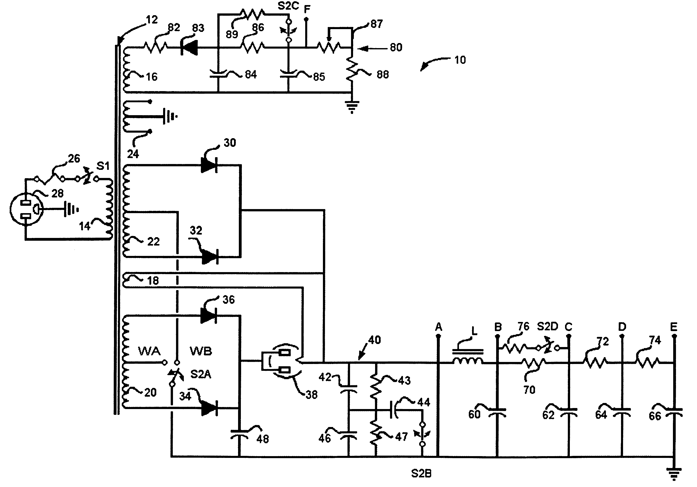
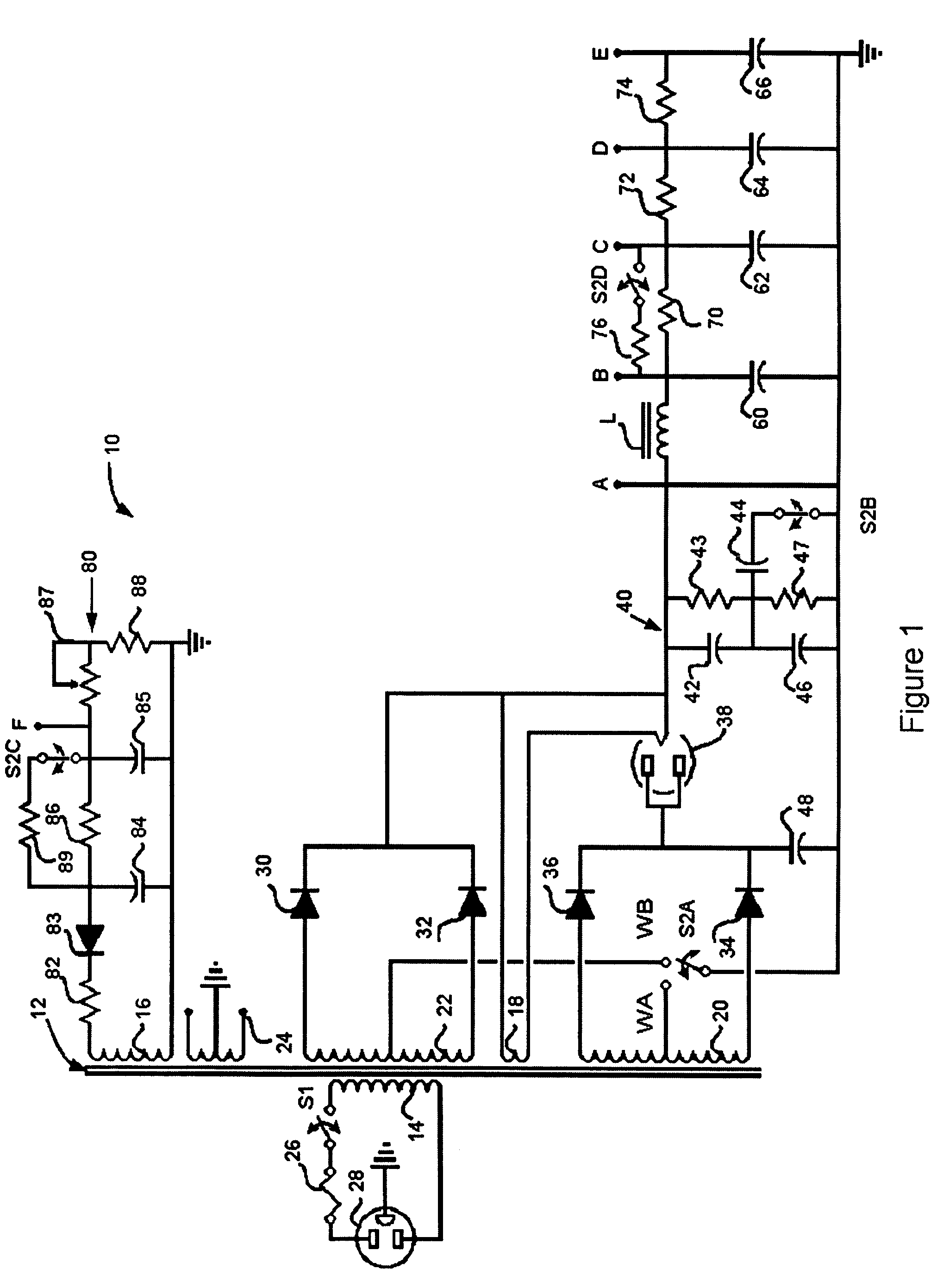
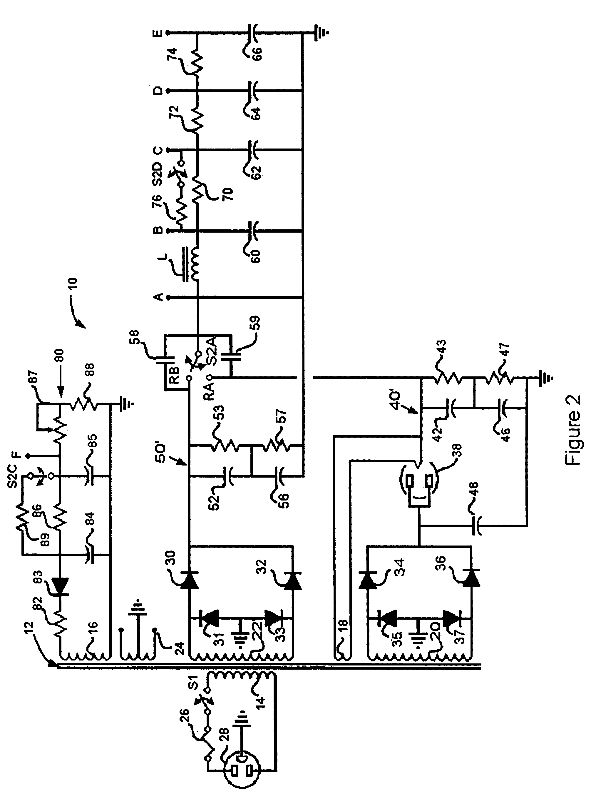
[0022]With joint reference to FIGS. 1 and 1a, an amplifier power supply 10 according to one preferred embodiment of the present invention is shown. The power supply 10 is capable of operation in, preferably, two modes: (1) referred to herein as the “punch” mode which is characterized by a relative voltage insensitivity to different current-demand conditions dictated by the connected audio amplifier; and (2) referred to herein as the “sag” mode which is characterized by a relative voltage sensitivity to different current-demand conditions dictated by the connected audio amplifier. These modes are user-selected to achieve differing sonic effects and are changed by a number of coordinated switches. The states of these switches for the embodiment of FIG. 1 are summarized in FIG. 1a and discussed in detail below.

[0023]As shown in FIG. 1, the inventive power supply may include a conventional connection 28 for receiving AC power, connected through a conventional fuse 26 and a power on / off ...


PUM


Abstract

The disclosure is directed to power supplies for audio amplifiers that focus on the importance of certain power supply characteristics in forming the overall qualities of a tube amplifier. The power supplies may use a power transformer with two dissimilar and selectable secondary windings to supply the voltages for a single vacuum tube power amplifier (B+ voltages). The power supplies may also apply different rectifier characteristics to complement the use of multiple differing secondary windings. The power supplies may also use different capacitor bank options to filter ripple voltage. The power supplies may also use of coordinated grid-bias voltage adjustment that coincides with secondary winding selection. The power supplies may also use coordinated preamp bias voltage adjustment that coincides with secondary winding selection.

Description

BACKGROUND OF THE INVENTION[0001]1. Field of the Invention[0002]The present invention is directed to systems, processes and apparatus for selecting from between multiple power supplies for use with audio amplifiers. More particularly, the invention relates to the field of electronic musical instrument amplifiers that enable selection from between multiple power supplies to achieve differing sonic effects. Accordingly, the general objects of the invention are to provide novel systems, methods and apparatus of such character.[0003]2. Description of the Related Art[0004]The development of audio amplifiers from the early days of electronics has tracked the development in electronics components in many ways. For example, audio amplifiers, which originally used vacuum tubes as amplifying and rectifying elements, widely migrated to semiconductor elements soon after such elements became available. Nonetheless, the use of vacuum tubes persists in several niche applications such as hi-fi ster...

Claims


Application Information

Patent Timeline
Patent Type & Authority Patents(United States)
IPC IPC(8): H03G3/00
CPCH03F3/02H03F3/181H03F2200/511H03F2200/507H03F2200/03
Inventor COCHRANE, PAUL
Owner MACLANE
Learn More