
Rail car mover apparatus for loader vehicle

a technology for moving rails and loaders, applied in the direction of locomotives, retractable wheels, transportation and packaging, etc., can solve the problems of significant modifications, significant increase in motive performance, and significant idle time of rail car movers, so as to reduce the pressure, reduce the weight of tires, and reduce the effect of rail wheels

Inactive Publication Date: 2006-01-24
BRANDT ROAD RAIL CORP
View PDF13 Cites 46 Cited by
  • Summary
  • Abstract
  • Description
  • Claims
  • Application Information

AI Technical Summary

Benefits of technology

[0011]It is an object of the present invention to provide a rail car mover adapter apparatus that overcomes problems in the prior art. It is a further object of the present invention to provide such an apparatus for a vehicle with a front end loader, such as a skid steer loader. It is a further object of the present invention to provide such an apparatus that is simple and economical, and that can conveniently be removed, in whole or in part, to allow the loader vehicle to perform conventional loader operations.
[0016]The actuators to move the rail wheels up and down are typically fluid cylinders, typically air or hydraulic cylinders. Propulsion is provided by the conventional loader tires which bear more or less of the vehicle's weight, depending on the pressure in the fluid cylinders. Where more traction is required, the pressure can be reduced thereby placing more weight on the tires and less on the rail wheels. Once the vehicle is moving, the traction requirement is generally reduced and the pressure can be increased to reduce weight on the tires at higher speeds, and thereby reduce wear on the rubber tires.
[0017]Conveniently the coupling adapter is attachable to the loader arms on the vehicle using the same quick-attach mechanism that is conventionally used to attach the loader bucket or like tools to the loader arms. It is well known to quick-attach jack-hammers, post-hole augers, grapples, compactors and various like tools to such loaders. The coupling adapter can conveniently be mounted in the same manner. The coupling hitch on the adapter has a closed bottom such that the loader arms can be raised to transfer weight from a coupled rail car to the loader vehicle, and thereby increase traction when required.
[0018]Conveniently, the apparatus can be configured so that the front rail wheels and the coupler adapter can be readily removed to allow normal loader vehicle operations. In many cases, the rear rail wheels could be left on without significant interference with loader operation, thereby further reducing time required to convert from rail to conventional mode. Alternatively, the rear rail wheels can also be readily removed. In addition to the rear rail wheels and fluid cylinders, often an air compressor and pressure tank to supply the fluid cylinders will be mounted to the rear bracket attached to the rear end of the loader vehicle. Removing the fasteners holding the rear bracket to the vehicle would remove the rear portion of the adapter apparatus.
[0019]Loader vehicles suitable for the conversion of the present invention are commonly found at industrial sites where rail car movers are also used. The rail car mover of the invention provides an economical adapter apparatus for converting such loader vehicles into rail car movers when required, and then converting back to normal loader operations when the rail car mover is not required.

Problems solved by technology

Some rail car movers are manufactured specifically for the purpose, and are capable of moving several loaded cars, however they are costly and often provide significantly more motive performance than is required.
It is not uncommon for rail car movers to sit idle for significant periods of time.
The rail car movers of Rannanmaki and Pyle do allow relatively economical conversion of a conventional vehicle, a tractor, into a rail car mover, however the modifications required are significant, and do not lend themselves to quick conversion to another purpose such as conventional use of the tractor on the ground.
As a result, these rail car movers converted from tractors often spend more time idle than working.

Method used


Image

  • Rail car mover apparatus for loader vehicle
  • Rail car mover apparatus for loader vehicle
  • Rail car mover apparatus for loader vehicle

Examples


Embodiment Construction

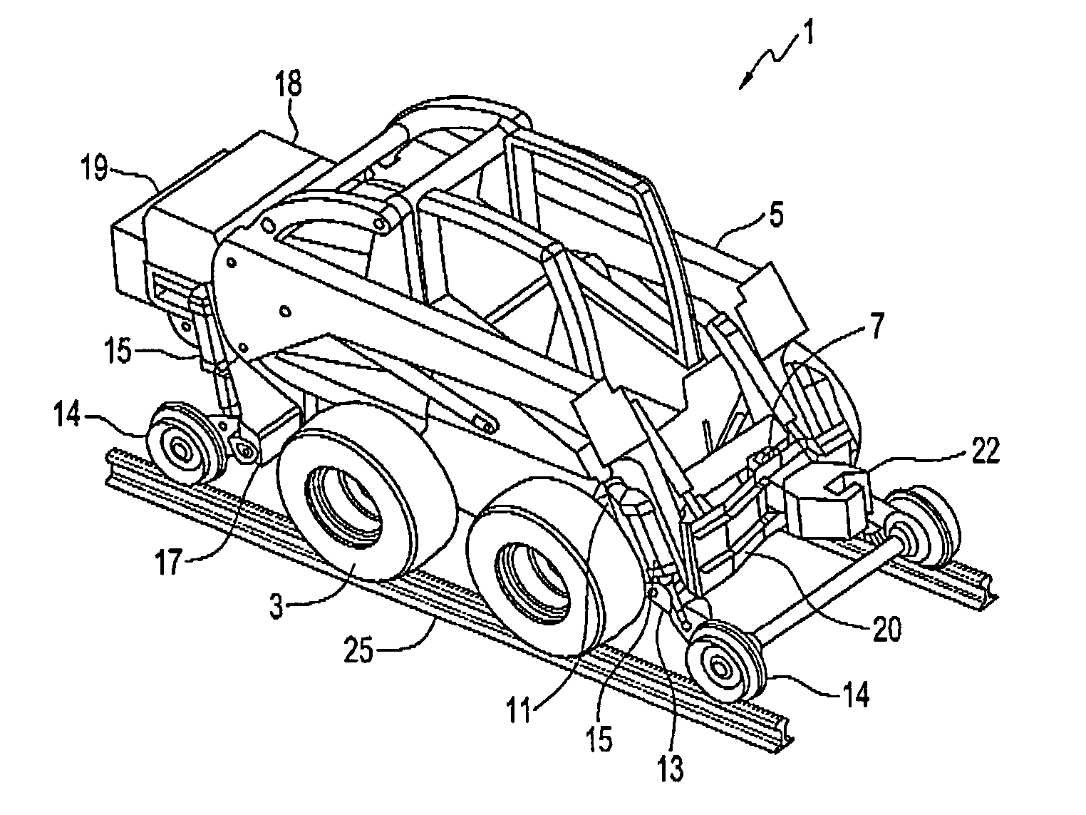
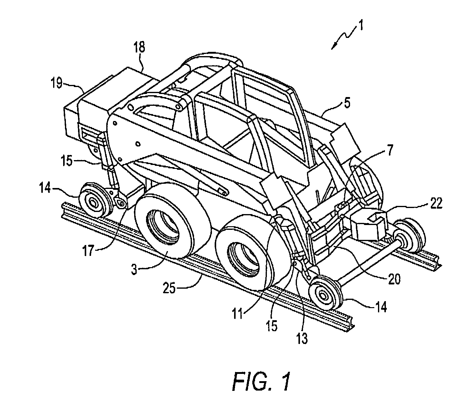
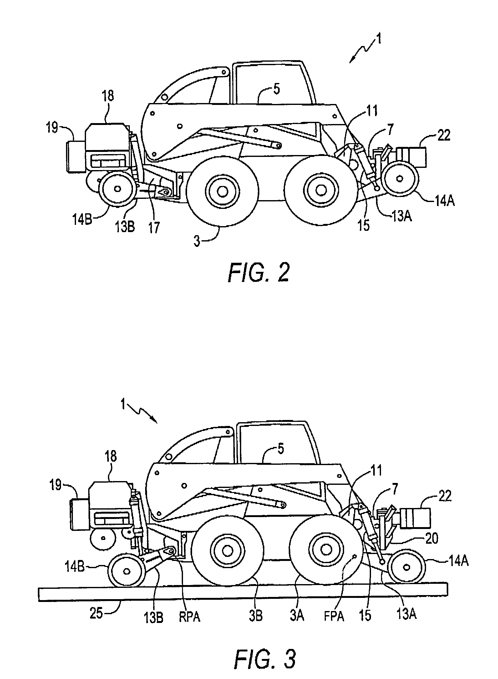
[0024]FIGS. 1–3 illustrate a skid steer loader vehicle 1 with a rail car mover adapter apparatus of the invention attached. The loader vehicle 1 conventionally includes wheels bearing ground tires 3, loader arms 5, and a tool attachment mechanism, such as the conventional quick-attach mechanism 7 located at the front of the loader arms 5 for attachment of a loader bucket, jack-hammer, post-hole auger, grapple, compactor, or other such tool. A skid steer vehicle steers by varying the speed of the wheels on one side compared to the other side, and thus has the advantage of maintaining the front and rear wheels in alignment on a rigid frame during use, and thus aligned with the rails. Other vehicle types could be used as well, as dictated by circumstances.

[0025]The adapter apparatus provides front and rear rail wheels 14 that move up and down to engage a pair of railroad rails 25. The illustrated adapter apparatus comprises a front wheel bracket 11 attached to the front of the loader v...


PUM


Abstract

A rail car mover apparatus for a loader vehicle comprises means to rotatably attach a pair of front rail wheels to a front end of the loader vehicle such that the front rail wheels are spaced to engage the pair of railroad rails and such that the front rail wheels can move up and down in response to forces exerted by a front actuator; means to rotatably attach a pair of rear rail wheels to a rear end of the loader vehicle such that the rear rail wheels are spaced to engage the pair of railroad rails and such that the rear rail wheels can move up and down in response to forces exerted by a rear actuator; and a coupler adapter adapted at a rear end thereof for attachment to a front portion of the loader arms and adapted at a front end thereof for coupling to a rail car hitch.

Description

[0001]This aplication claims the benefit of Provisional App. No. 60 / 421,694, filed Oct. 28, 2002.[0002]This invention is in the field of vehicles for road and railway use, and in particular such vehicles for moving rail cars.BACKGROUND[0003]Rail car movers are used to maneuver rail cars around yards, plants, and like industrial sites. Such rail car movers vary considerably in size, complexity, and cost depending on the number and weight of rail cars being moved, maneuverability required, and so forth.[0004]Some rail car movers are manufactured specifically for the purpose, and are capable of moving several loaded cars, however they are costly and often provide significantly more motive performance than is required. Such rail car movers are disclosed in U.S. Pat. Nos. 4,497,257 and 4,537,137 to White, Jr., and U.S. Pat. No. 4,843,973 to Hartelius et al. Typically these have rail wheel sets and road wheel sets configured such that one set is entirely raised out of contact so that the ...

Claims


Application Information

Patent Timeline
Patent Type & Authority Patents(United States)
IPC IPC(8): B61C11/00B60F1/04B61D15/00
CPCB60F1/043E02F9/022B61D15/00B60F2301/04
Inventor MARCOTTE, NEILBURT, BARRY
Owner BRANDT ROAD RAIL CORP
Learn More