
Pulley of washing machine

a technology of washing machine and pulley, which is applied in the direction of washing machine with receptacles, mechanical control devices, cranks, etc., can solve the problems of damage to the motor, heavy load on the motor, etc., and achieve the effect of high tensile strength

Inactive Publication Date: 2008-08-26
LG ELECTRONICS INC
View PDF10 Cites 9 Cited by
  • Summary
  • Abstract
  • Description
  • Claims
  • Application Information

AI Technical Summary

Benefits of technology

The present invention is about a pulley for a washing machine that reduces the weight of the pulley by using a high-rigidity material in a strain-focused portion of the pulley. This reduces the load on the motor and improves the efficiency of the washing machine. The pulley is made of a composite member that includes a wheel and an axle piece made of different materials with different tensile strengths. The axle piece has teeth that increase the contact surface area and disperse the mechanical energy transmitted through the pulley. The pulley is formed by an insertion molding process. The technical effects of the invention are a reduction in weight of the pulley, improved efficiency of the washing machine, and increased contact surface area for transmitting power.

Problems solved by technology

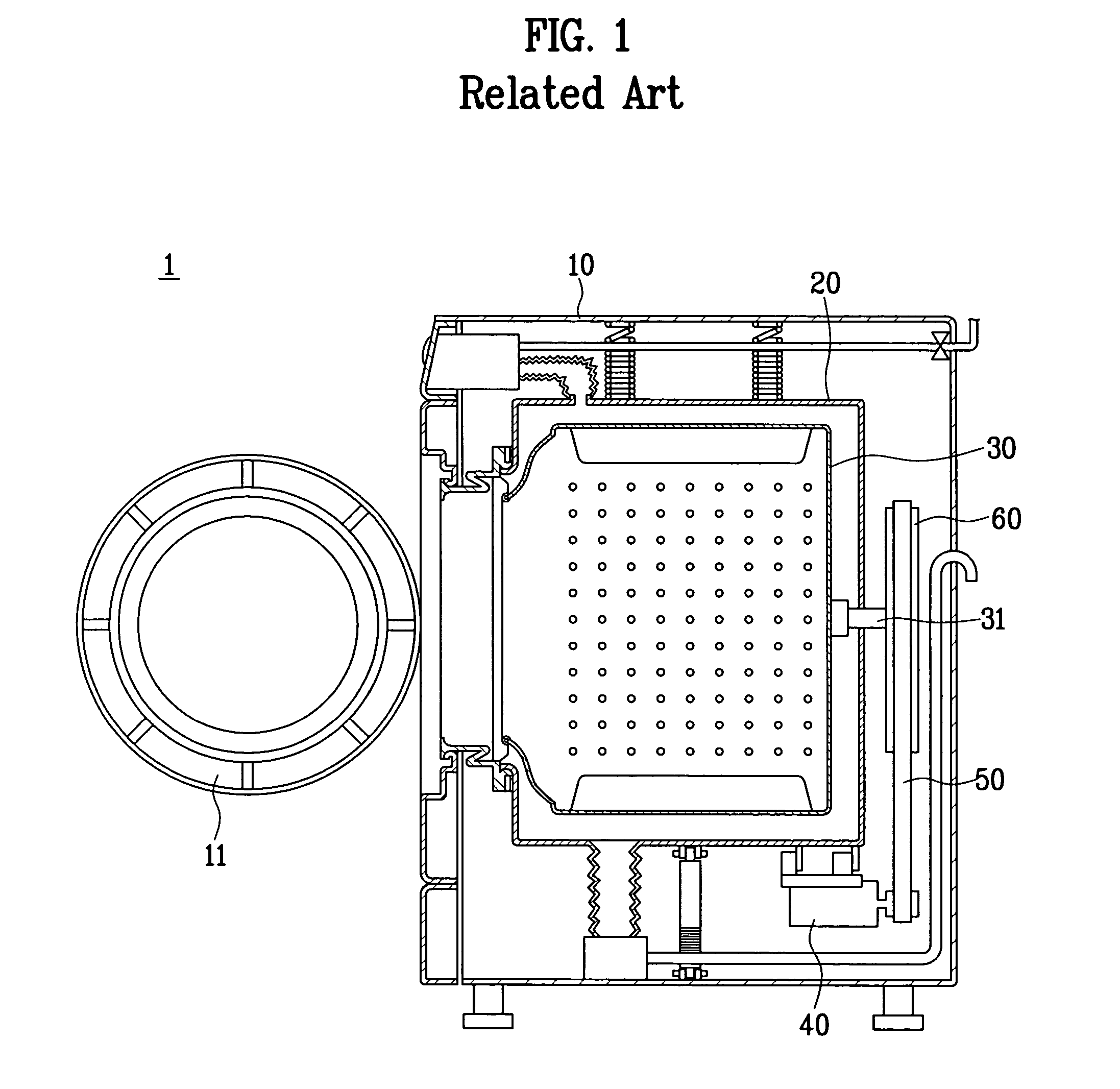
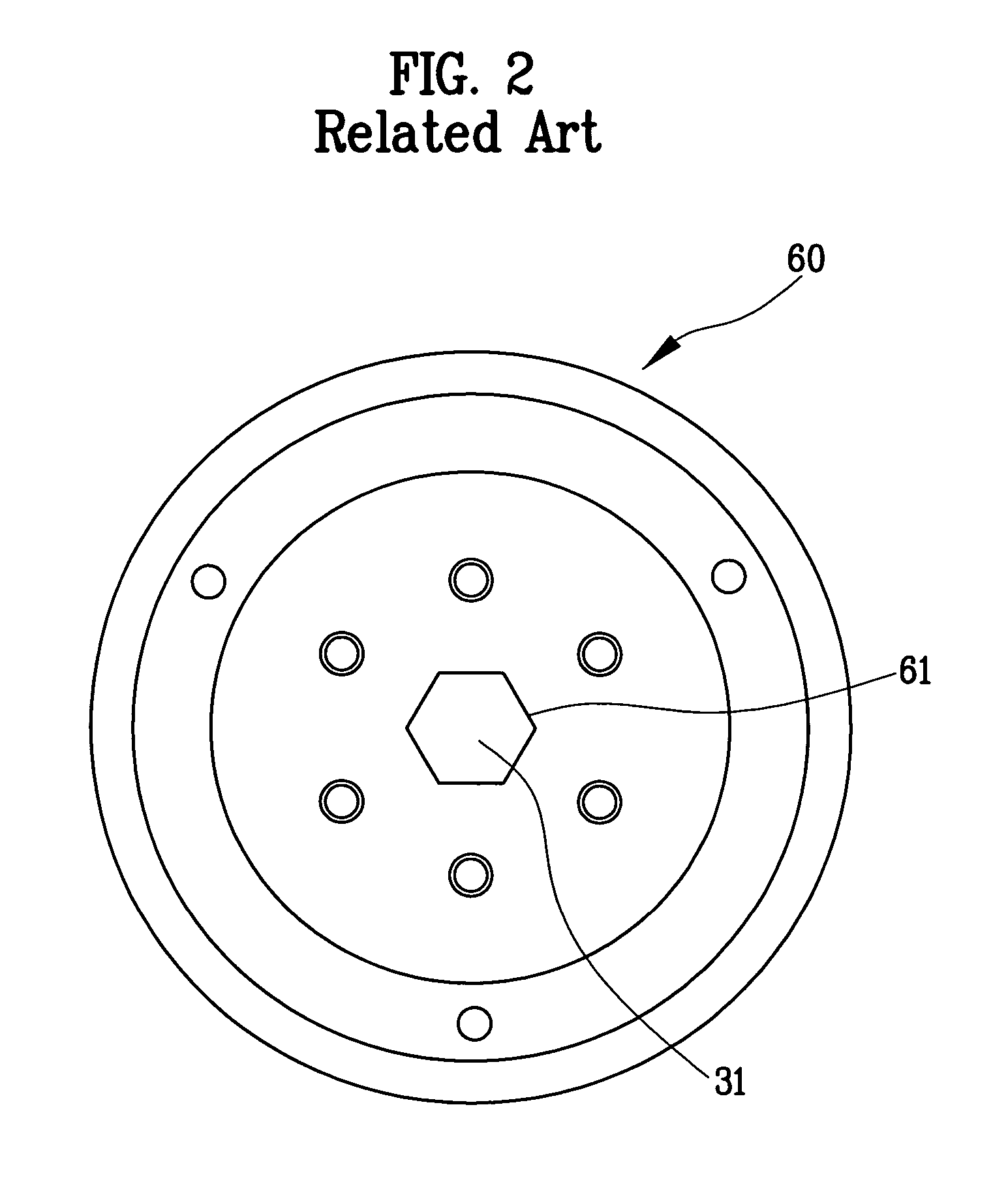
However, the related art pulley of the washing machine is formed of the steel based material, thereby becoming heavy to impose a load on the motor.
Hence, damage is caused to the motor.

Method used


Image

  • Pulley of washing machine
  • Pulley of washing machine
  • Pulley of washing machine

Examples


Embodiment Construction

[0021]Reference will now be made in detail to the preferred embodiments of the present invention, examples of which are illustrated in the accompanying drawings. Throughout the drawings, like elements are indicated using the same or similar reference designations where possible.

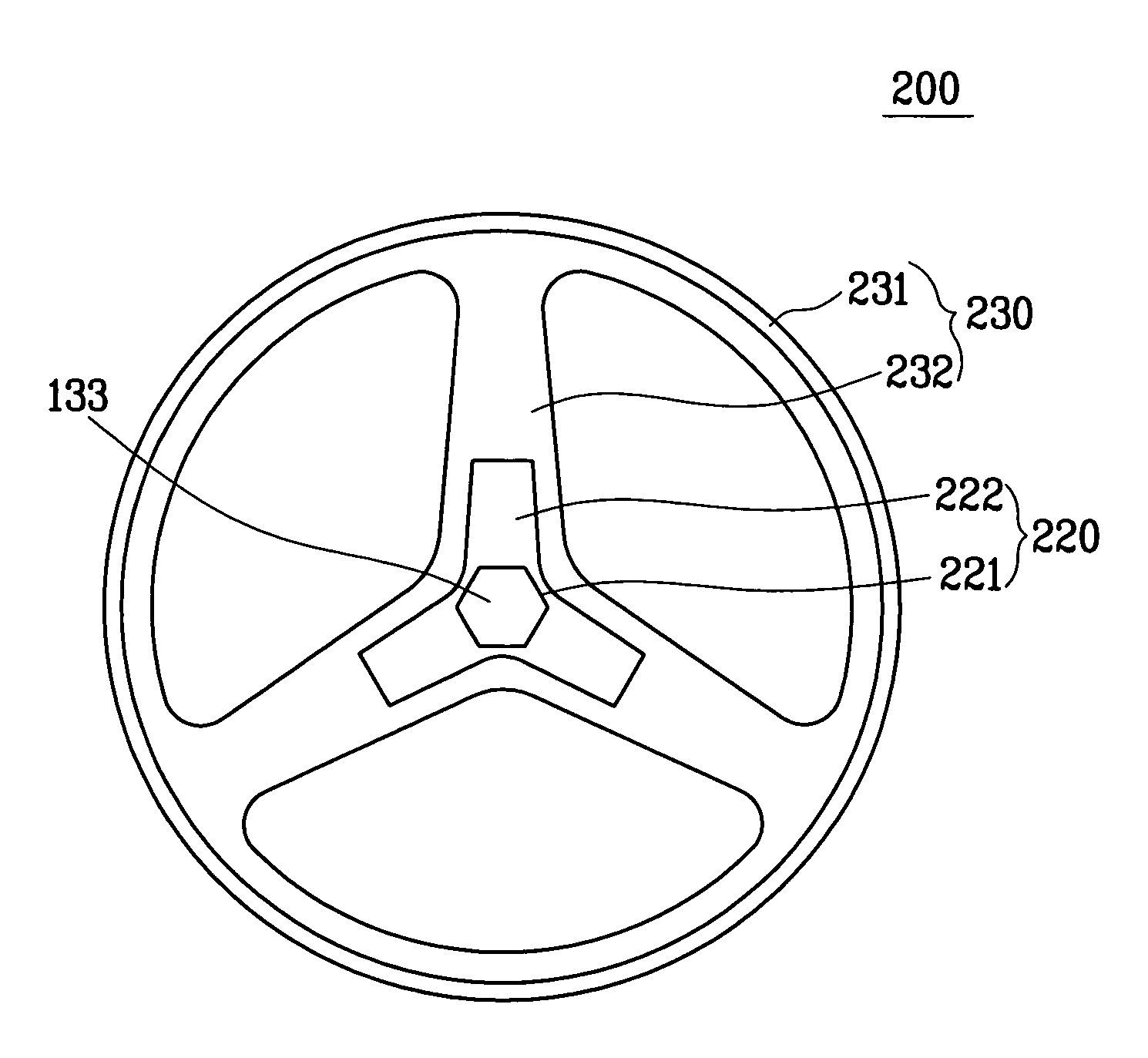
[0022]FIG. 3 is a cross-sectional diagram of a washing machine according to the present invention, and FIG. 4 is a front diagram of a pulley according to the present invention. Referring to FIG. 3, a case 110 forms an exterior of a washing machine 100 according to the present invention. A tub 120 is suspended within the case 110. For this, an upper part of the tub 120 is connected to a spring 140 fixed to the case 110 and a lower part of the tub 120 is connected to a damper 150 connected to a bottom surface of the case 110 via a hinge. The above-provided spring 140 and damper 150 play a role in attenuating vibration appearing on the tub 120 in the course of operating a washing machine as well as elastically s...


PUM


Abstract

A pulley of a washing machine, wherein the weight of the pulley is reduced by forming a strain-focused portion of the pulley with a high-rigidity material. The pulley of the washing machine having a motor for rotating a drum connected to one end of a shaft, includes a composite member, axially coupled to the other end of the shaft, for transferring a rotational force of the motor to the drum, the composite member being formed of at least two materials having dissimilar tensile strengths.

Description

[0001]This application claims the benefit of Korean Application No. P2004-007891, filed on Feb. 6, 2004, which is hereby incorporated by reference.BACKGROUND OF THE INVENTION[0002]1. Field of the Invention[0003]The present invention relates to a washing machine, and more particularly, to a pulley of a washing machine transferring a rotational force generated from a motor to a drum.[0004]2. Discussion of the Related Art[0005]Generally, a washing machine is a representative home appliance for removing filth or dirt attached to a laundry using a reaction between water and detergent. A washing machine is categorized into various types according to an impacting mechanism on a laundry. FIG. 1 is a cross-sectional diagram of a washing machine according to a related art. Referring to FIG. 1, a washing machine 1 consists of a case 10 forming an exterior and having a door 11 on its front side, a tub 20 fixed within the case 10, a drum 30 rotatably provided within the tub 20, and a motor 40 ro...

Claims


Application Information

Patent Timeline
Patent Type & Authority Patents(United States)
IPC IPC(8): D06F37/00D06F37/04D06F37/30
CPCD06F37/30Y10T74/2115Y10T74/2132H02K7/1004F16H55/36
Inventor KIM, YOUNG SOO
Owner LG ELECTRONICS INC
Learn More