
Dynamic, on-demand storage area network (SAN) cache

a storage area network and cache technology, applied in the field of storage area networks, can solve the problems of limited cache memory, high cost of systems, and inability to offer the performance levels of high-end systems, and achieve the effect of facilitating caching and enhancing flexibility

Active Publication Date: 2008-08-19
CISCO TECH INC
View PDF18 Cites 10 Cited by
  • Summary
  • Abstract
  • Description
  • Claims
  • Application Information

AI Technical Summary

Benefits of technology

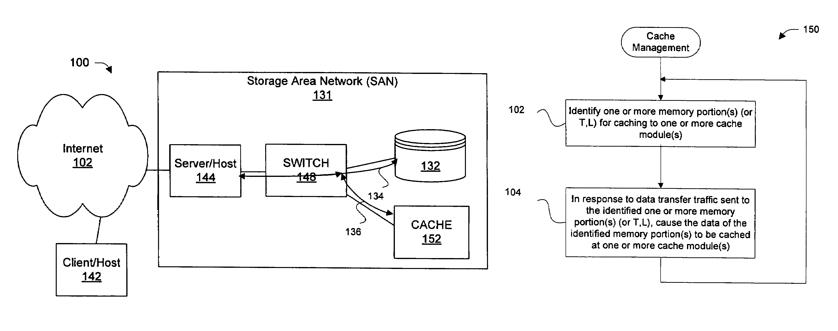
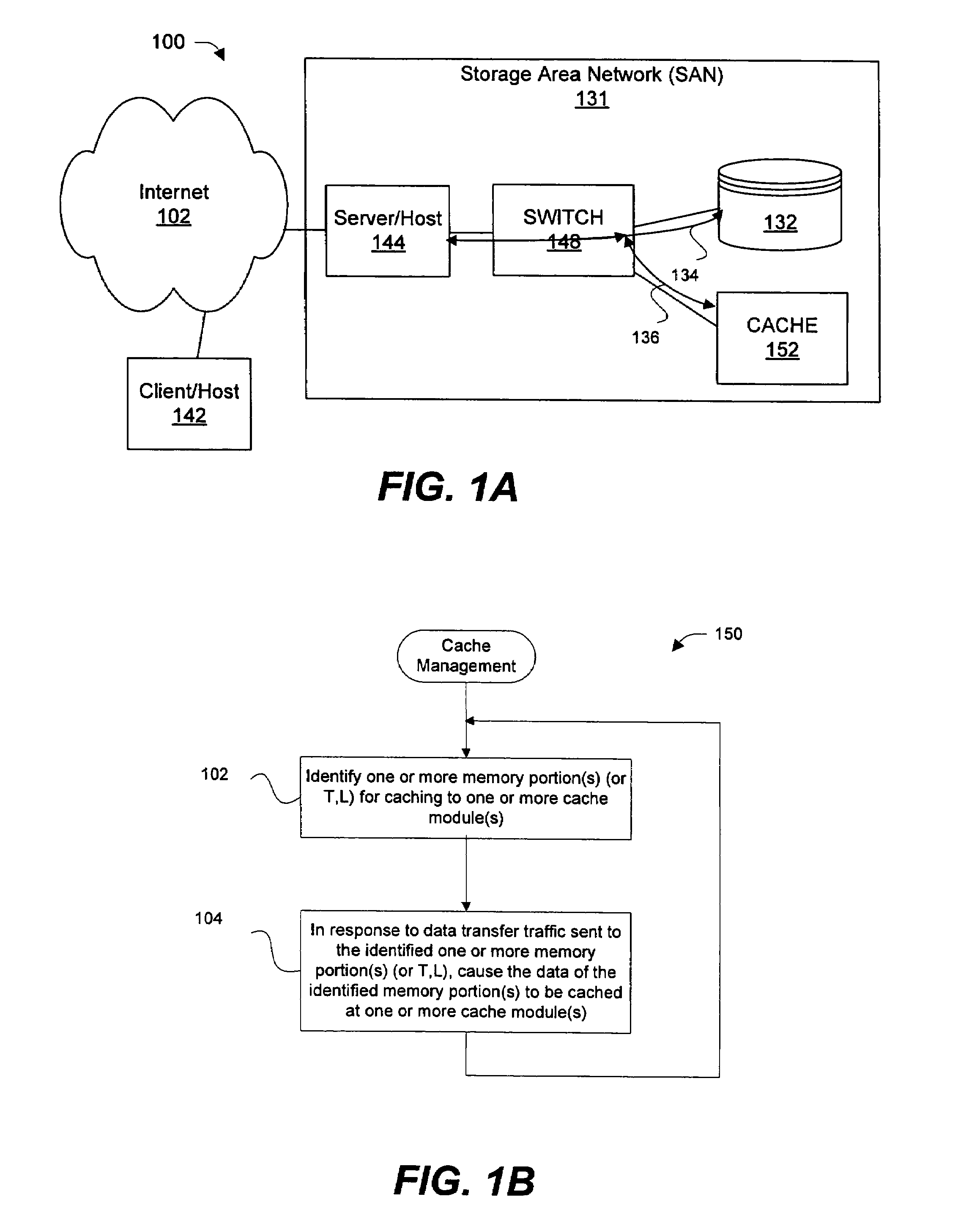
[0005]The present invention provides apparatus and methods for facilitating caching in a storage area network (SAN). In general, a memory portion of a storage device (e.g., target and LUN or T,L) is identified for caching in a specified cache module. In response to data transfer traffic that is sent to the identified memory portion, data that resides in such identified memory portion is then caused to be cached in the identified cache module or another cache module that is associated with such identified cache module. One or more network devices (e.g., switches) of the SAN are configured to at least initiate the caching. As needed, data transfer traffic for any number of memory portions and storage devices can be identified for (or removed from) caching to a particular cache module. Also, any number of cache modules can be utilized for data caching so that data from any number of memory portions and / or storage devices can be divided among such cache modules in any suitable proportion for enhanced flexibility.

Problems solved by technology

However, these systems are extremely expensive.
In contrast, mid-range storage systems have limited amount of cache memory (e.g., a few GBs) and can not offer the performance levels of high end systems.
There is also a utilization related problem in a SAN formed from a high number of mid-range storage systems.
Unfortunately, the caches in both of the mid-range and high end systems are not sharable beyond the systems in which they reside.
Accordingly, if the sum of caches of all those idling systems is a significant number, a significant amount of cache memory is unutilized.

Method used


Image

  • Dynamic, on-demand storage area network (SAN) cache
  • Dynamic, on-demand storage area network (SAN) cache
  • Dynamic, on-demand storage area network (SAN) cache

Examples


Embodiment Construction

[0031]Reference will now be made in detail to a specific embodiment of the invention. An example of this embodiment is illustrated in the accompanying drawings. While the invention will be described in conjunction with this specific embodiment, it will be understood that it is not intended to limit the invention to one embodiment. On the contrary, it is intended to cover alternatives, modifications, and equivalents as may be included within the spirit and scope of the invention as defined by the appended claims. In the following description, numerous specific details are set forth in order to provide a thorough understanding of the present invention. The present invention may be practiced without some or all of these specific details. In other instances, well known process operations have not been described in detail in order not to unnecessarily obscure the present invention.

[0032]FIG. 1A is block diagram illustrating a simplified network 100 in which various embodiments of the inv...


PUM


Abstract

Disclosed are apparatus and methods for facilitating caching in a storage area network (SAN). In general, data transfer traffic between one or more hosts and one or more memory portions in one or more storage device(s) is redirected to one or more cache modules. One or more network devices (e.g., switches) of the SAN can be configured to redirect data transfer for a particular memory portion of one or more storage device(s) to a particular cache module. As needed, data transfer traffic for any number of memory portions and storage devices can be identified for or removed from being redirected to a particular cache module. Also, any number of cache modules can be utilized for receiving redirected traffic so that such redirected traffic is divided among such cache modules in any suitable proportion for enhanced flexibility.

Description

BACKGROUND OF THE INVENTION[0001]The present invention relates to storage area networks. More particularly, the present invention relates to methods and apparatus for providing cache storage in a storage area network (SAN).[0002]A particular SAN has different cost and performance aspects based on the type of storage systems deployed. The high end storage systems like EMC Symmetrix, DMX, Hitachi 9960s, IBM Shark, etc. have customized hardware designed for scalability of memory size (e.g., can provide hundreds of GB) and performance. However, these systems are extremely expensive.[0003]In contrast, mid-range storage systems have limited amount of cache memory (e.g., a few GBs) and can not offer the performance levels of high end systems. There is also a utilization related problem in a SAN formed from a high number of mid-range storage systems. Unfortunately, the caches in both of the mid-range and high end systems are not sharable beyond the systems in which they reside. Assuming tha...

Claims


Application Information

Patent Timeline
Patent Type & Authority Patents(United States)
IPC IPC(8): G06F12/00
CPCG06F12/0813G06F12/0873H04L67/2842H04L67/1097G06F2212/314G06F2212/263H04L67/568
Inventor RAO, RAGHAVENDRA J.BASAVAIAH, MURALIPARIKH, URSHITCHANDRASEKARAN, VARAGUR
Owner CISCO TECH INC
Learn More