Cutter assembly

Inactive Publication Date: 2008-08-12
TSAI SHI LING
View PDF5 Cites 5 Cited by
  • Summary
  • Abstract
  • Description
  • Claims
  • Application Information

AI Technical Summary

Benefits of technology

[0005]Accordingly, an objective of the present invention is to provide a cutter assembly whose blade discs can be installed and removed more conveniently than the prior arts.

Problems solved by technology

The extraneous steps of removing the bearings, bearings seats, and the nuts inevitably affect the production speed.
This will make the maintenance of the cutter assembly more inconvenient and costly as, when one blade disc is damaged, it has to be replaced by one of the same type as the damaged one.

Method used


Image

  • Cutter assembly
  • Cutter assembly
  • Cutter assembly

Examples


Embodiment Construction

[0024]The following descriptions are exemplary embodiments only, and are not intended to limit the scope, applicability or configuration of the invention in any way. Rather, the following description provides a convenient illustration for implementing exemplary embodiments of the invention. Various changes to the described embodiments may be made in the function and arrangement of the elements described without departing from the scope of the invention as set forth in the appended claims.

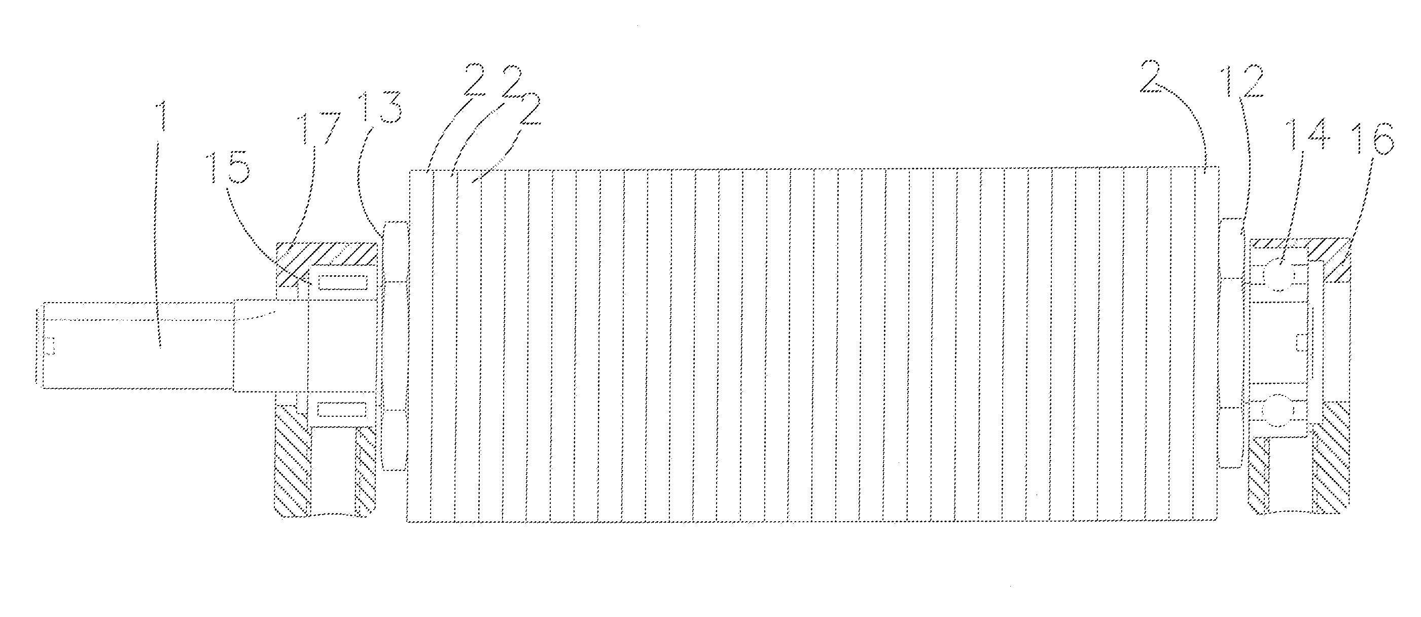
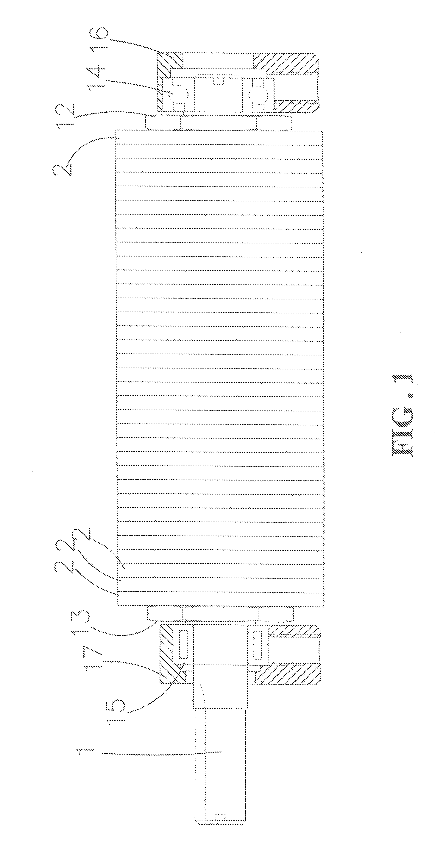
[0025]As shown in FIG. 1, a cutter assembly according to an embodiment of the present invention contains an axle 1. As further shown in FIGS. 2 and 3, the axle 1 has a number of parallel, equally spaced troughs 11 along the axial direction. The cutter assembly further contains a number of circular blade discs 2, each having a center hole (not numbered) threaded through by the axle 1. As shown in FIG. 8, each blade 2 has a number of teeth 21 along the circumference of the center hole corresponding an...


PUM


Abstract

The cutter assembly contains an axle having a number of parallel, equally spaced troughs along the axial direction, and a number of circular blade discs, each having a center hole threaded through by the axle. Each blade disc has a number of teeth along the circumference of the center hole corresponding and matching to the troughs of the axle. The blade disc has fewer blades than the teeth and the blade discs therefore can be mounted on the axle in different orientations so that their blades are spirally arranged. The axle of the cutter assembly has a fixed end and the blade discs can be sequentially installed to or removed from the other free end. The bearing at the free end has a smaller diameter so that the blade discs can be removed or installed directly passing through the bearing without removing it first.

Description

(A) TECHNICAL FIELD OF THE INVENTION[0001]The present invention generally relates to cutter assemblies for wood planing and cutting, and more particularly to a cutter assembly having easily replaceable blade discs.(B) DESCRIPTION OF THE PRIOR ART[0002]A number of cutter assemblies whose blades are spirally arranged have already been taught in the prior art. These spiral cutter assemblies usually contain a number of blade discs threaded by an axle through their centers. The advantage of these spiral cutter assemblies is that, if one blade disc is damaged, only that blade disc needs replacement, instead of the entire cutter assembly.[0003]Usually these cutter assemblies are supported at the axle's two ends by bearings and bearing sets so that the axle and therefore the spirally arranged blades can freely spin. Within the pair of bearings, the blade discs are usually sandwiched and confined between two nuts at the two ends of the axle. To replace a damaged blade disc, therefore, requir...

Claims


Application Information

Patent Timeline
IPC IPC(8): B26D1/12
CPCB23C5/04B27G13/005B23C2210/244Y10T407/1952Y10T407/1926Y10T407/1942Y10T407/1815Y10T407/191
Inventor TSAI, SHI-LING
Owner TSAI SHI LING
Why Eureka
Try Eureka