
Sway-type micro-actuator with slider holding arms for a disk drive head gimbal assembly

a technology of gimbal assembly and micro-actuator, which is applied in the direction of maintaining head carrier alignment, recording information storage, instruments, etc., can solve the problems of affecting the ability of the slider to accurately read data from and write data to the disk, and having a very difficult manufacturing process. , to achieve the effect of fine head position adjustmen

Inactive Publication Date: 2008-08-05
SAE MAGNETICS (HK) LTD
View PDF32 Cites 48 Cited by
  • Summary
  • Abstract
  • Description
  • Claims
  • Application Information

AI Technical Summary

Benefits of technology

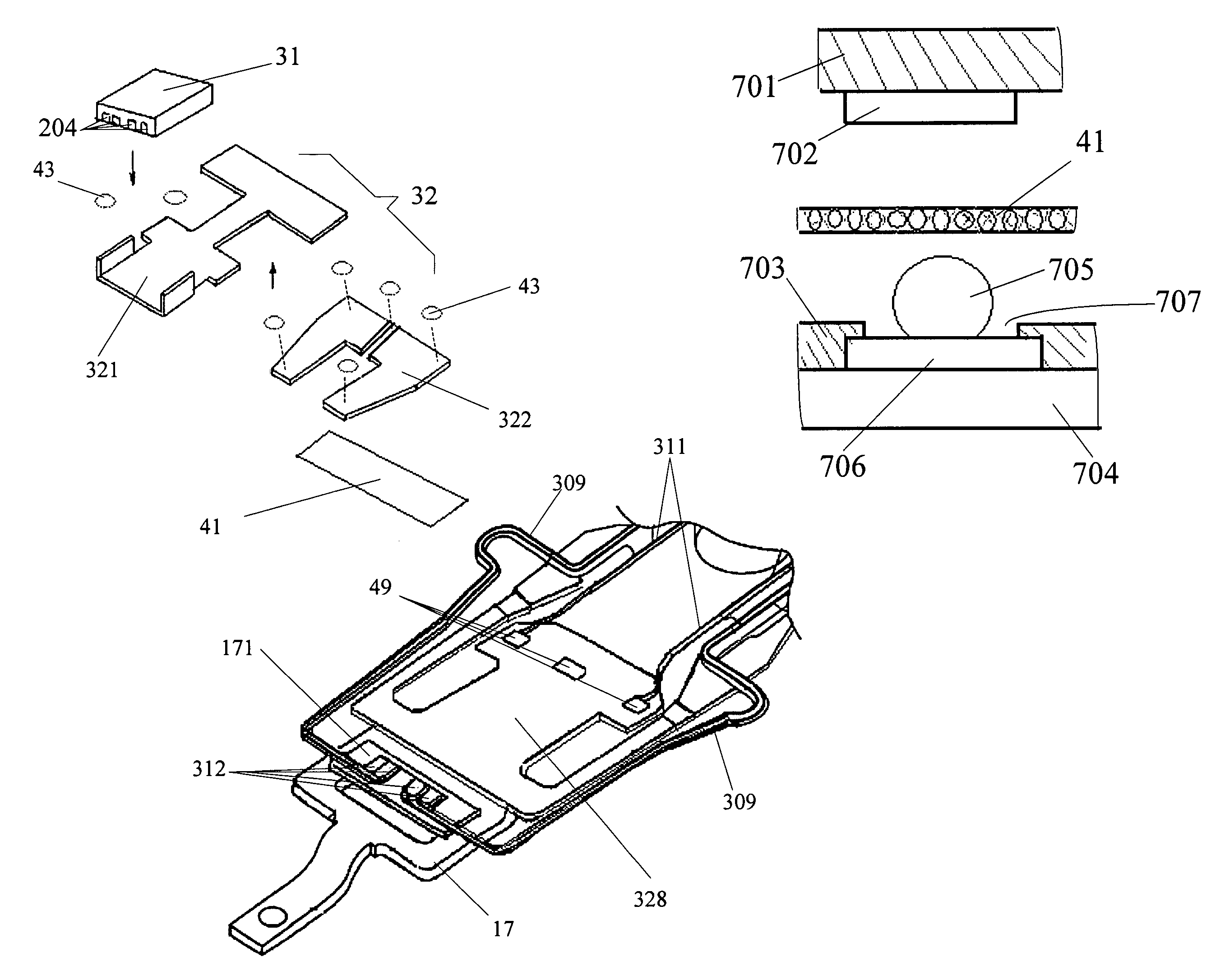
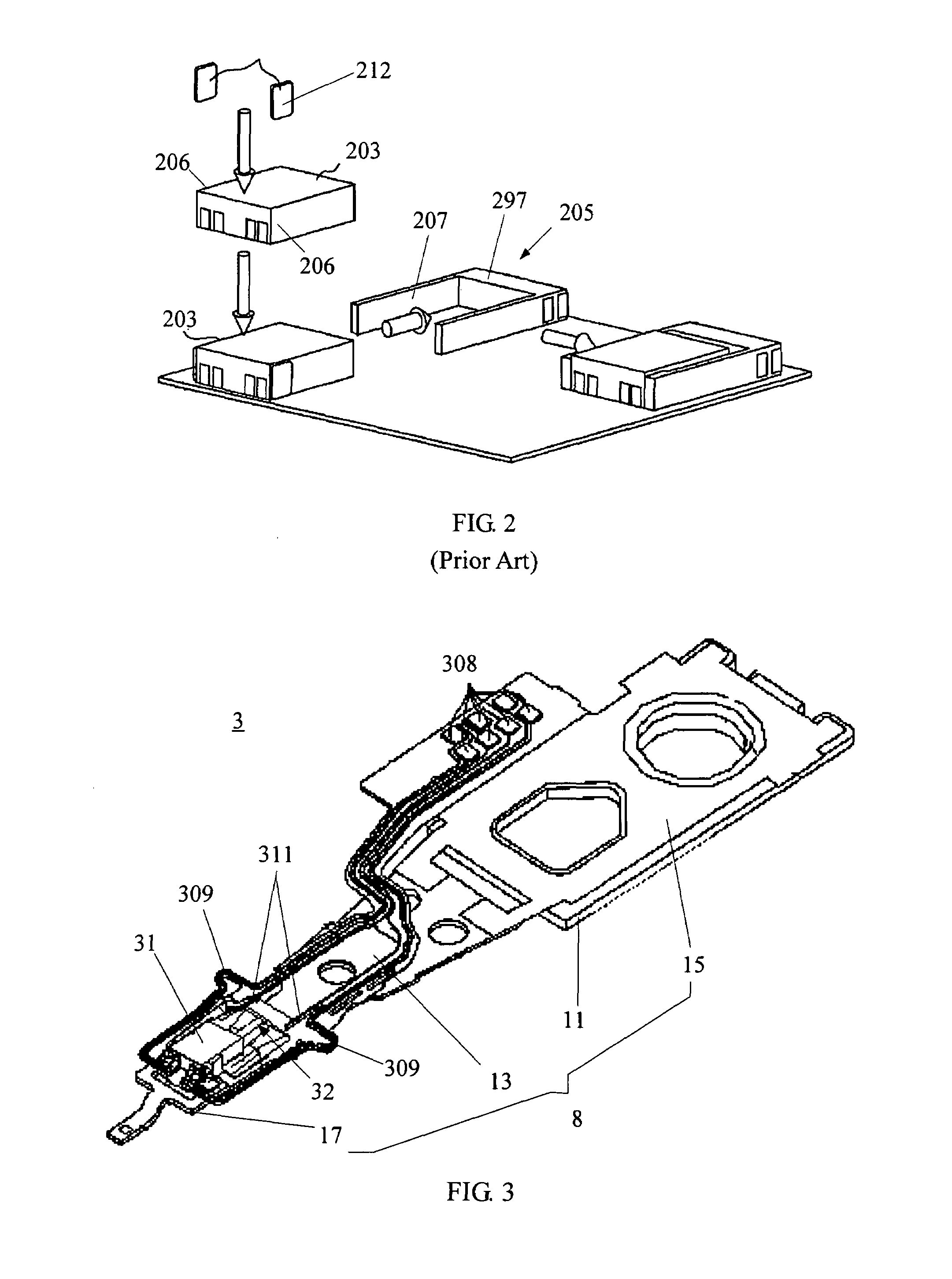
The present invention provides a micro-actuator and a disk drive unit with improved head position adjustment and reliable electrical connection between the micro-actuator and the suspension. The micro-actuator includes a support frame with two slider holding arms that can define the position of the slider and prevent it from undue movement. The support frame is made of metal, which improves shock performance and prevents particle contamination. The manufacture process is simple and can control the static attitude of the micro-actuator. The invention also reduces the voltage required to operate the thin film PZT micro-actuator and achieves the same displacement as prior art micro-actuators.

Problems solved by technology

However, Because of the inherent tolerance (dynamic play) resulting from VCM that exists in the placement of the slider, the slider cannot achieve quick and fine position control which adversely impacts the ability of the slider to accurately read data from and write data to the disk.
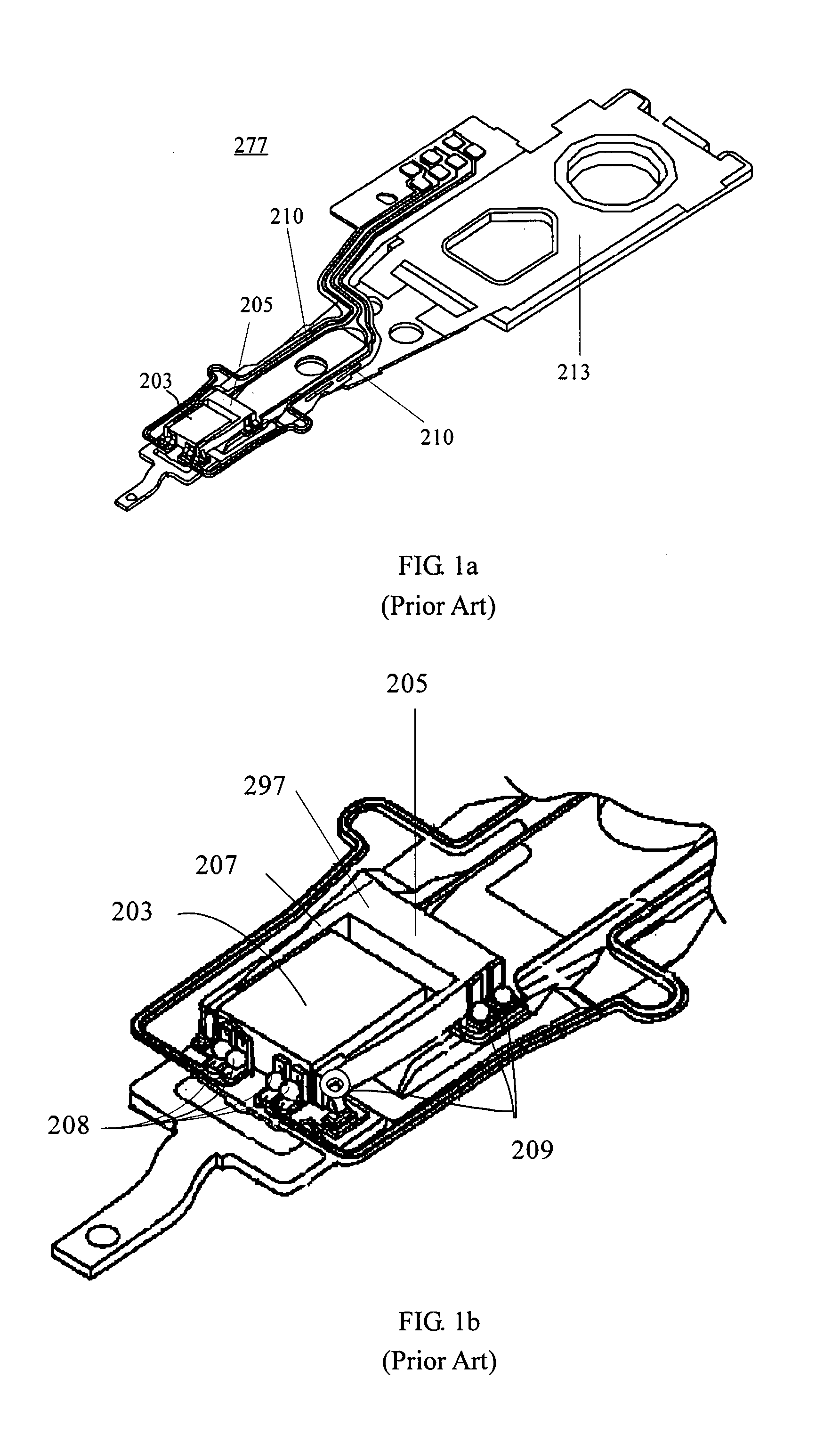
However, the HAG 277 with the micro-actuator 205 is very difficult to manufacture.
Also, because the U-shaped frame 297 of the micro-actuator 205 are very brittle so as to produce a not perfect shock performance.
In addition, it is also a other problem that no effective solution to identify the potential micro crack of the U-shaped frame 297.
Both will influence the static attitude of the HAG 277 and accordingly increase the difficulty of manufacturing the HAG 277.
However, this cleaning method cannot be used in the above-mentioned HAG 277 because there is a potential danger to damage the U-shaped frame 297 of the micro-actuator 205.

Method used


Image

  • Sway-type micro-actuator with slider holding arms for a disk drive head gimbal assembly
  • Sway-type micro-actuator with slider holding arms for a disk drive head gimbal assembly
  • Sway-type micro-actuator with slider holding arms for a disk drive head gimbal assembly

Examples


Embodiment Construction

[0042]Various preferred embodiments of the present invention will now be described with reference to the figures. As indicated above, the present invention is designed to provide a micro-actuator with improved structure for the purpose of fine tuning the position of the slider. The improved micro-actuator comprises a support frame with two slider holding arms, the two slider holding arms can define the position of the slider so as to prevent the slider from unduly movement and thus attain a more accurate head position adjustment. In addition, the present invention also provides a new method to electrically bond the micro-actuator with a HAG suspension. The bonding methods will attain a more reliable electrical connection between the micro-actuator with the HAG suspension. Several example embodiments of the invention will now be described. It is noted that the invention is not limited to such implementations. Instead, the micro-actuator of the invention can be implemented in any suit...


PUM

PropertyMeasurementUnit
lengthaaaaaaaaaa
conductiveaaaaaaaaaa
piezoelectricaaaaaaaaaa

Abstract

A micro-actuator of the invention includes a support frame having a base, a moving plate, a leading beam to connect the base with the moving plate; and two slider holding arms extending from both sides of the moving plate; at least one piezoelectric element bonding to the support frame to connect a free end of the base with the moving plate; wherein the moving plate sways in a first direction or in a second direction when the at least one piezoelectric element is actuated. The invention also discloses a head gimbal assembly and a disk drive unit using the micro-actuator.

Description

FIELD OF THE INVENTION[0001]The present invention relates to a disk drive unit, and more particularly to a micro-actuator and a head gimbal assembly (HAG) with such an micro-actuator.BACKGROUND OF THE INVENTION[0002]Disk drives are information storage devices that use magnetic media to store data. A traditional disk drive includes a magnetic disk and a drive arm for driving a HAG with a slider mounted thereon. The disk is mounted on a spindle motor which causes the disk to spin. A primary actuation, such as voice-coil motor (VCM) is provided for controlling the motion of the drive arm and, in turn, controlling the slider to move from track to track across the surface of the disk, thereby enabling the slider to read data from or write data to the disk. In operation, a lift force is generated by the aerodynamic interaction between the slider and the spinning magnetic disk. The lift force is opposed by equal and opposite spring forces applied by the suspension of the HAG such that a pr...

Claims


Application Information

Patent Timeline
Patent Type & Authority Patents(United States)
IPC IPC(8): G11B5/596G11B5/48
CPCG11B5/4853G11B5/4826
Inventor YAO, MINGGAOSHIRAISHI, MASASHI
Owner SAE MAGNETICS (HK) LTD
Learn More