
High-frequency power amplifier module

a power amplifier and high-frequency technology, applied in gated amplifiers, amplifiers with semiconductor devices only, amplifiers with semiconductor devices, etc., can solve the problems of less stable amplifiers, and achieve low isolation between the amplifiers, lowering operation efficiency, and reducing the effect of operational efficiency

Inactive Publication Date: 2008-08-05
RENESAS ELECTRONICS CORP
View PDF11 Cites 9 Cited by
  • Summary
  • Abstract
  • Description
  • Claims
  • Application Information

AI Technical Summary

Benefits of technology

[0009]In the known arrangement in which switches are used to selectively use plural output stage amplifiers, the switches contribute to lowering the efficiency of operation, but isolation between the output stage amplifiers connected in parallel is enhanced. In the another known arrangement in which output stage amplifiers are selectively used using no switches, lowering of the operational efficiency due to switches does not take place, but, with high-power amplifiers and low-power amplifiers always interconnected in terms of high frequencies, isolation between the amplifiers is low and the amplifiers are less stable.
[0010]An object of the present invention is to provide a highly stable high-frequency power amplifier module with high isolation between output amplifiers.

Problems solved by technology

In the another known arrangement in which output stage amplifiers are selectively used using no switches, lowering of the operational efficiency due to switches does not take place, but, with high-power amplifiers and low-power amplifiers always interconnected in terms of high frequencies, isolation between the amplifiers is low and the amplifiers are less stable.

Method used


Image

  • High-frequency power amplifier module
  • High-frequency power amplifier module
  • High-frequency power amplifier module

Examples


embodiment 1

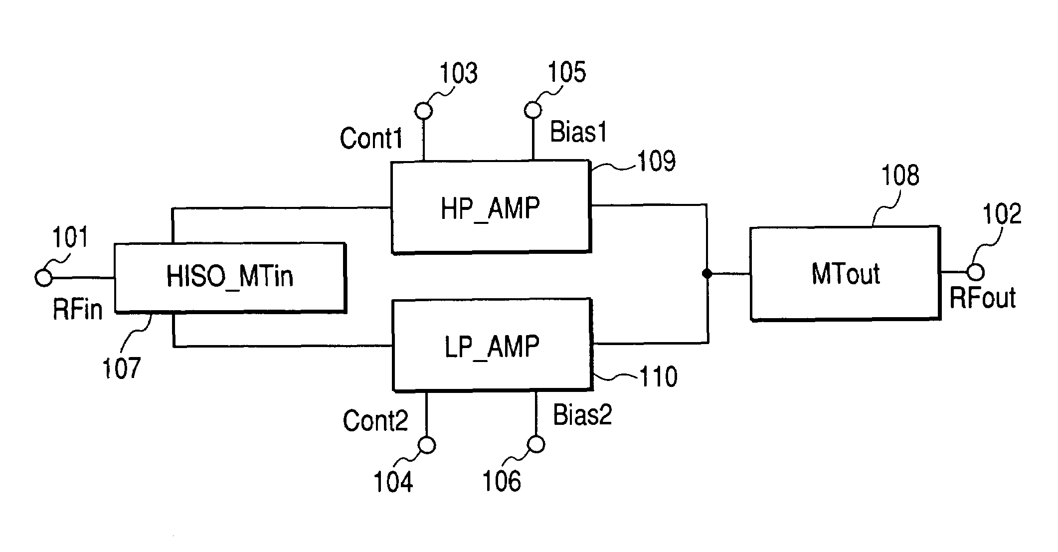
[0022]FIG. 1 is a circuit block diagram showing a configuration of a high-frequency power amplifier module according to the present invention. A high-frequency power is input to a high-frequency input (RFin) terminal 101 and is transmitted, via a high-isolation, input matching circuit (HISO_MTin) 107, to a high-power amplifier section (HP_AMP) 109 or a low-power amplifier section (LP_AMP) 110 to be amplified there. The amplified high-frequency power is then output, after passing an output matching circuit (MTout) 108, from a high-frequency output (RFout) terminal 102. The high-isolation input matching circuit may be, for example, a Wilkinson divider.

[0023]Activating the low-power amplifier section 110 and deactivating the high-power amplifier section 109 of the high-frequency power amplifier module is possible by turning off either or both of a bias input terminal (Cont1) 103 and a bias output terminal (Bias1) 105 of the high-power amplifier section 109 and turning on both of a bias...

embodiment 2

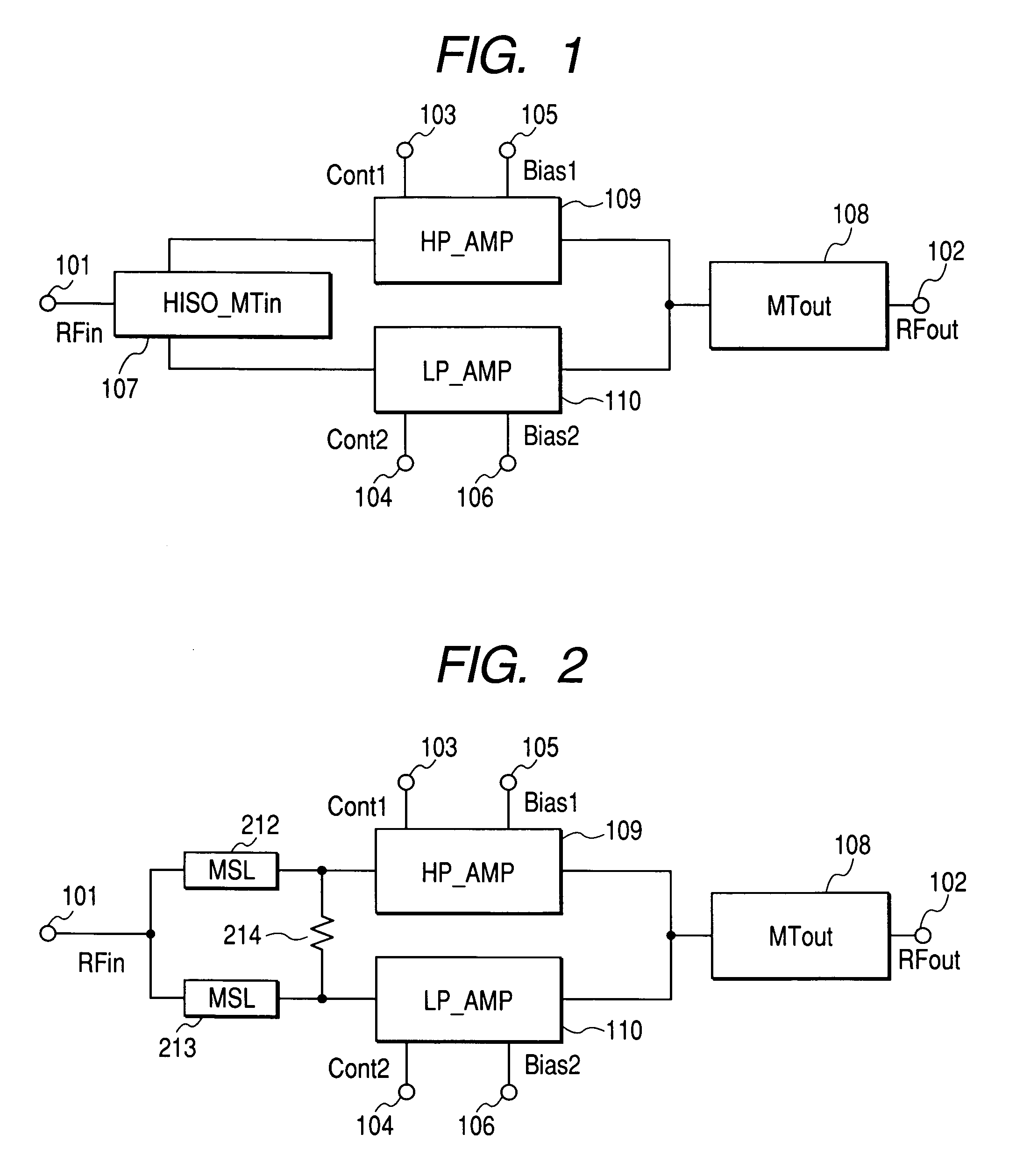
[0028]FIG. 2 is a circuit block diagram showing a configuration of a high-frequency power amplifier module according to a second embodiment of the present invention. The configuration is the same as the configuration shown in FIG. 1 with the high-isolation input matching circuit 107 replaced by a distributed constant Wilkinson circuit.

[0029]In this embodiment, distributed constant lines (MSLs) 212 and 213 and a resistance 214 make up the distributed constant Wilkinson circuit. In this case, it is not necessarily required that either or both of the line impedance and the electrical length are the same between the distributed constant lines 212 and 213. In other words, impedances and / or distributions at Wilkinson divider terminals may be different for the low-power amplifier section 110 and the high-power amplifier section 109.

[0030]This is because the amplification gain or the input impedance is not necessarily the same between the high-power amplifier section 109 and the low-power a...

embodiment 3

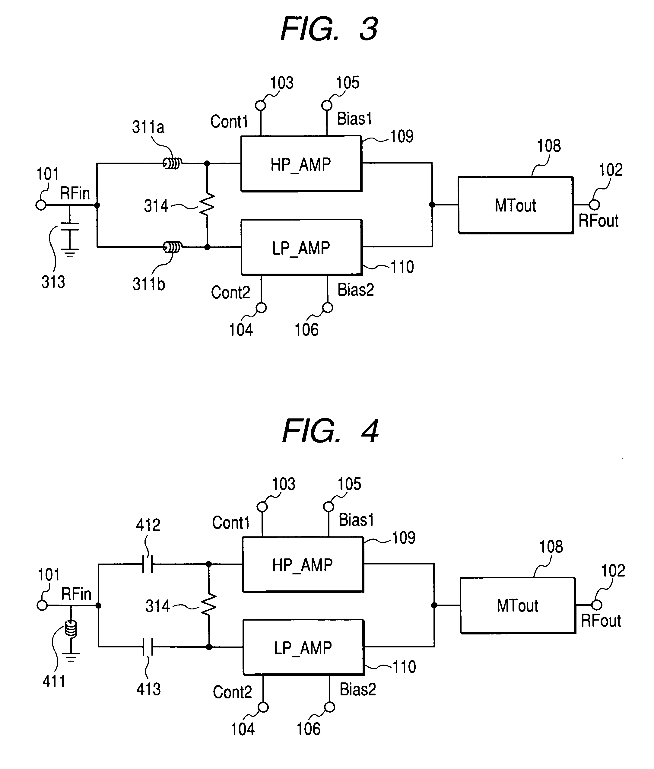
[0032]FIG. 3 is a circuit block diagram showing a configuration of a high-frequency power amplifier module according to a third embodiment of the present invention. The configuration is the same as the configuration shown in FIG. 1 with the high-isolation input matching circuit 107 replaced by a lumped constant Wilkinson circuit. In this embodiment, inductances 311a and 311b, a capacitance 313, and a resistance 314 make up the lumped constant Wilkinson circuit. In this case, the inductances 311a and 311b need not necessarily be of a same value. A high-frequency power is input to the high-frequency input terminal 101 and is transmitted, via the lumped constant Wilkinson circuit, to the high-power amplifier section 109 or the low-power amplifier section 110. The subsequent operation is the same as in the configuration shown in FIG. 1. The effects of this embodiment are also similar to those obtained from the configuration shown in FIG. 1.


PUM


Abstract

For use in an amplifier configuration including a high-power amplifier and a low-power amplifier which are always interconnected in terms of high frequencies and between which switching is made using no switches, a highly stable high-frequency power amplifier module with high isolation between the amplifiers is provided. To reduce wrapping around from a low-power amplifier section in an activated state to a high-power amplifier section in a deactivated state or from the high-power amplifier section in an activated state to the low-power amplifier section in a deactivated state, an input matching circuit having high isolation characteristics is included in an input matching circuit portion which does not have much to do with amplifier efficiency. Switching of each of the amplifier sections between an activated state and a deactivated state is effected by control using bias input terminals.

Description

CLAIM OF PRIORITY[0001]The present application claims priority from Japanese application JP 2004-272945 filed on Sep. 21, 2004, the content of which is hereby incorporated by reference into application.FIELD OF THE INVENTION[0002]The present invention relates to a high-frequency power amplifier for use in a transmitter section of radio communication equipment such as mobile telephones. More particularly, it relates to a high-frequency power amplifier module in which switching between a high-power amplifier and a low-power amplifier can be made by bias control.BACKGROUND OF THE INVENTION[0003]In recent years, in the field of mobile communications, not only mobile terminals but also base stations are required to be made smaller and lighter. In this respect, since the power amplifier sections of relevant equipment greatly affect the sizes and weights of the equipment, it is important to improve efficiency of the power amplifier sections. Mobile terminals, in particular, are normally po...

Claims


Application Information

Patent Timeline
Patent Type & Authority Patents(United States)
IPC IPC(8): H03F1/14H03F3/191
CPCH03F1/0277H03F3/72H03F3/191H03F2203/7206
Inventor OHNISHI, MASAMITANOUE, TOMONORIMATSUMOTO, HIDETOSHI
Owner RENESAS ELECTRONICS CORP
Learn More