Super high floating line
a floating line and super high technology, applied in the direction of synthetic resin layered products, fishing, transportation and packaging, etc., can solve the problems of low specific gravity of fly fishing lines, difficult casting, and microspheres utilized in the lines, and achieves less specific gravity, more durable, and more supple
- Summary
- Abstract
- Description
- Claims
- Application Information
AI Technical Summary
Benefits of technology
Problems solved by technology
Method used
Image

Examples
first embodiment
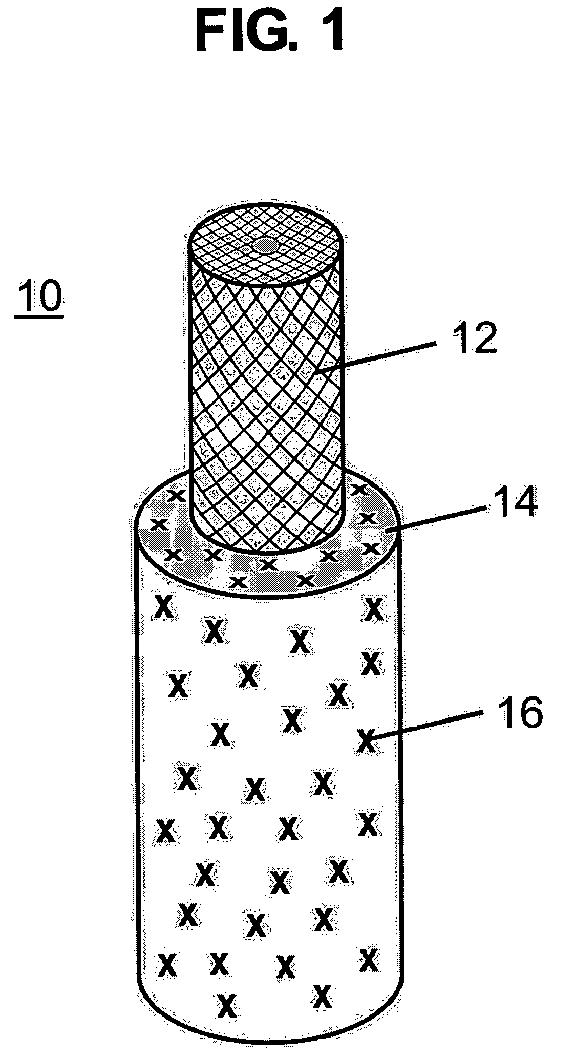
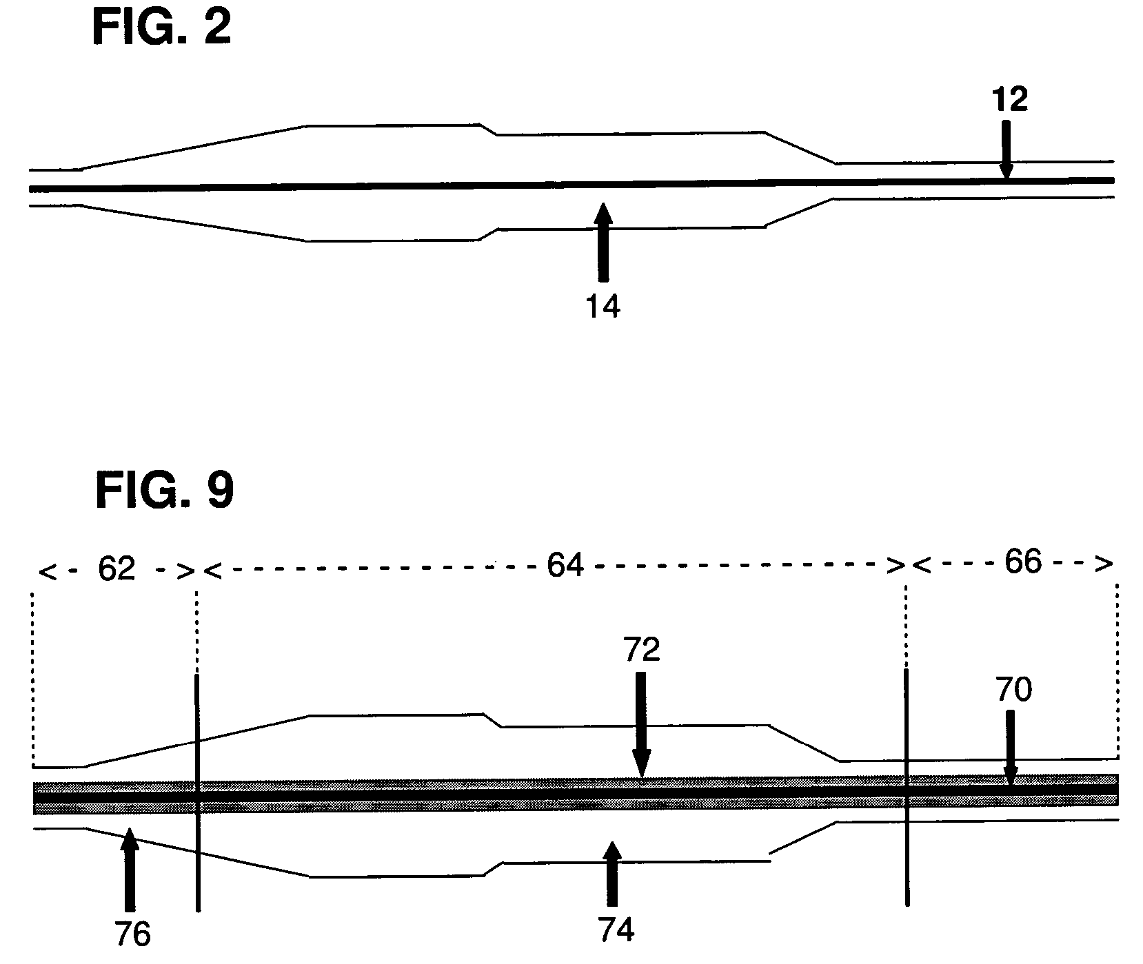
[0050]Referring to the drawings and particularly to FIG. 1 thereof, a fly line in accordance with the invention is schematically shown. As shown, fly line 10 is comprised of an inner core 12 and an outer coating 14 disposed over the core. Core 12 is made of one or more filaments, such as a nylon monofilament or a nylon braided multifilament, which are well known. Core 12 may be made of other suitable materials. Outer coating 14 preferably is a PVC plastisol, but may be made of other suitable materials such as polyurethane.
[0051]In accordance with the present invention, coating 14 includes microspheres 16 (shown as “X”s in FIG. 1) dispersed throughout the coating, with each microsphere 16 comprising a polymer shell that encapsulates a small amount of a hydrocarbon gas (also called “polymer microspheres” herein). Each polymer microsphere 16 thus features a small amount of a hydrocarbon gas encapsulated in a gastight thermoplastic (polymer) shell. Examples of suitable gas filled micros...
second embodiment
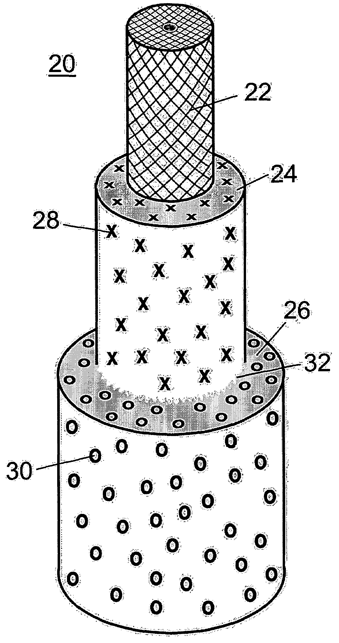
[0064]Referring now to FIGS. 3 and 4 of the drawings, a fly line in accordance with the invention is schematically shown. FIG. 3 is a perspective schematic illustration of fly line 20 shown with various layers partially removed, and FIG. 4 is a cross-sectional view of fly line 20. Fly line 20 has a core 22, an inner coating 24 disposed over core 22, and an outer coating 26 disposed over inner coating 24.
[0065]Like core 12 in the first embodiment, core 22 is made of one or more filaments, preferably a nylon monofilament or a nylon braided multifilament. Inner coating 24 (also called “first coating” or “first inner coating”) preferably is a PVC plastisol. Outer coating 26 (also called “second coating” or “second outer coating”) also preferably is a PVC plastisol.
[0066]In accordance with the present invention, the PVC plastisol of inner coating 24 includes polymer microspheres 28 (shown as “X”s in FIGS. 3 and 4)), that is, the previously described microspheres with hydrocarbon encapsul...
fourth embodiment
[0073]FIG. 9 shows an exemplary fly line in accordance with the present invention. As shown, fly line 60 comprises multiple coatings and includes a floatation tip 62, a body 64 and a running line 66. Fly line 60 includes a core 70, which preferably is nylon monofilament or nylon multifilament and preferably has a diameter of between 0.018 inches an 0.028 inches, generally depending on the size of the line. Both floatation tip 62 and running line 66 preferably have overall diameters between 0.035 inches and 0.045 inches, and body 64 has a preferred diameter of between 0.045 inches and 0.115 inches, generally depending on the size and taper of the line. Fly line 60 includes an inner coating 72 that extends through the floatation tip 62, body 64 and running line 66. Inner coating 72 preferably has a constant thickness of around 0.003 inches and is 0.006 inches larger than the core size independent of line size, taper or core diameter.
[0074]In accordance with the present invention, fly ...
PUM
| Property | Measurement | Unit |
|---|---|---|
| specific gravities | aaaaa | aaaaa |
| specific gravity | aaaaa | aaaaa |
| specific gravity | aaaaa | aaaaa |
Abstract
Description
Claims
Application Information
 - R&D
- Intellectual Property
- Life Sciences
- Materials
- Tech Scout
- Unparalleled Data Quality
- Higher Quality Content
- 60% Fewer Hallucinations
Browse by: Latest US Patents, China's latest patents, Technical Efficacy Thesaurus, Application Domain, Technology Topic, Popular Technical Reports.
© 2025 PatSnap. All rights reserved.Legal|Privacy policy|Modern Slavery Act Transparency Statement|Sitemap|About US| Contact US: help@patsnap.com